XFEM4U Manual
| Copyright | Copyright © 2025 XFEM4U |
Welkom bij XFEM4U
XFEM4U is het gereedschap voor alle ingenieurs.
Met XFEM4U kun je snel en eenvoudig de geometrisch lineaire of geometrisch niet-lineaire krachtenverdeling in jouw constructie bepalen. Het programma is zeer gebruiksvriendelijk, modern en zeer snel.
XFEM4U heeft een volledig geïntegreerde beton-, staal- en houtmodule, waarin de beton, staal- en houtconstructie ook worden getest volgens EN1992, EN1993 resp. EN1995.
XFEM4U creëert een uitgebreid en leesbaar berekeningsrapport als MS/Word document (*.DOCX) of als PDF-document. XFEM4U creëert een volledig transparante sterkteberekening die jij als constructeur kunt controleren.
Voor de beton-, staal- en houtmodule betekent dit dat alle toegepaste (Eurocode) formules volledig worden weergegeven inclusief alle actuele parameters. Dit geeft jou inzicht in de berekening. Jouw sterkteberekening wordt zonder problemen geaccepteerd door keurende instanties.
Menu
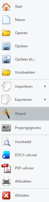
- Projectgegevens
- Voorbeeld
- Back-up Bestanden
- Export / Import:
- SNDF
- DXF
- IFD
- TXT
- XML
- XFEM4U Import
- IDEAStatiCa
Ribbonmenu
- Aanpak
- Navigeren in 3D
- Sneltoetsen
- Dokbare Vensters / Verplaatsbare Tabellen
- Afmetingen Wijzigen
- Balkrooster Beton
Algemeen
Geometrie
- Staven / Starre Verbindingen
- Profielen
- Vloeren / Platen
- Knooppunten
- Verbindingen
- Hulplijnen
- Rasterlijnen / Niveaus
- Buitenpanelen
- Wizard
- Intern Scharnier in een Balk
Belastingen
- Belastinggenerator
- Belastinggevallen
- Balkbelastingen
- Knooppuntbelastingen
- Knooppuntverplaatsingen
- Oppervlaktebelastingen
- Belastingcombinaties
- Volgorde Belastingcombinaties
Bewerken
Weergave
Resultaten
Toewijzen
Toewijzen - Algemeen
Toewijzen - Knooppunten
Toewijzen - Staven
- Profielsectie
- Balk Vrijgaven
- Lokale As
- Belastingoverdracht Optie
- Balk Invoegpunt
- Kipstabiliteit
- Eigen Gewicht
Toewijzen - Platen
Selecteren
Selecteren - Algemeen
- Alles Selecteren
- Selectie Omkeren
- Selectie Wissen
- Vorige Selectie Ophalen
- Op Coördinaatbereik
- Alle Losse Knooppunten
- Op Laag
Selecteren - Knooppunten
Selecteren - Staven
- Alle Staven Selecteren
- Op Nummer
- Op Materiaal
- Op Profielsectie
- Evenwijdig aan
- Verbonden met Knooppunten
- Verbonden met Staven
- Op Vlak
- Alleen Trek
- Starre Verbinding
- Dummy
Selecteren - Platen
Selecteren - Belastingpaneel
Video Tutorial
Linten
Werkwijze
XFEM4U heeft een zeer gebruikersvriendelijk en intuïtieve ‘user interface ’. Deze eigentijdse ‘user interface ’ zorgt voor een snelle invoer. Je zult ervaren hoe eenvoudig en ook hoe plezierig het is om met XFEM4U te werken.
Je kunt jouw constructie volledig grafisch en/of via tabellen invoeren. Het maakt niet uit! Ook kun je tussentijds wisselen tussen grafische invoer en tabellarische invoer.
Knopen, Opleggingen, Lokaal assenstelsel
Staven
Belastingen, Belastingsgevallen, Staafbelastingen, Knoopbelastingen, Knoopverplaatsingen Vlakbelasting
Navigeren in 3D
Voor het navigeren in jouw 3D model worden 2 gangbare methoden ondersteund. Je kunt instellen welke je wilt gebruiken. Tabblad Instellingen & Handleiding > Instellingen > tabblad Navigeren. Zie Navigeren
1. Methode zoals in Autodesk Revit (standaard)
- In- en uitzoomen: Gebruik het muiswieltje.
- Verslepen: Druk het muiswieltje in en versleep.
- Draaien: Druk het muiswieltje en SHIFT-toets tegelijk in en versleep.
2. Methode zoals in Tekla structures
- In- en uitzoomen: Gebruik het muiswieltje.
- Verslepen: Druk het muiswieltje in en versleep.
- Draaien: Druk het muiswieltje en CNTRL-toets tegelijk in en versleep.
Opmerking: XFEM4U ondersteunt ook het gebruik van een 3d muis (van bijvoorbeeld 3dconnection) waarmee je nog makkelijker en sneller werkt.

Sneltoetsen
Het is ook mogelijk om met sneltoetsen te werken.
Bijna alle commando's kun je nu net als in Autocad - Revit ook met 2 letters aanroepen.
De twee letters, vaak een afkorting van het commando (zoals BE voor "Add Beam" of LQ voor "Add beam Load Q"), maken het logisch en snel aan te leren, zelfs voor beginners. Wij hebben die sneltoetsen al voor je gemaakt. En met het menu of met de letters KS (Keyboard Shortcuts) kun je die lijst van sneltoetsen opvragen.
Met sneltoetsen hoef je je hand niet steeds van het toetsenbord naar de muis te verplaatsen. Dit bespaart elke keer enkele seconden, wat zich op een werkdag optelt tot uren aan tijdwinst.
Om het laatste teken commando te herhalen druk je op de Enter-toets of de spatiebalk zoals in AutoCAD, of F4-toets zoals MS Word. Dit is superhandig omdat je vaak het tekenen van bijvoorbeeld een nieuwe staaf snel wilt herhalen. Het grote voordeel is dat je niet je muis hoeft te bewegen naar de functie in het menu zodat je nog makkelijker en sneller jouw invoer kunt maken.
General
| Sneltoets | Beschrijving |
|---|---|
| KS | Shows this overview of Keyboard Shortcuts |
| Ctrl+Z | Undo |
| Ctrl+Y | Redo |
| Return- / Enter- / Spacebar- / F4-key | Repeats the last command |
| Escape-key | Interrupt |
File
| Sneltoets | Beschrijving |
|---|---|
| Ctrl+N | New file |
| Ctrl+O | Open file |
| Ctrl+S | Save file |
| Ctrl+P | Print file |
| PV | PreView |
Geometry
| Sneltoets | Beschrijving |
|---|---|
| BE | BEam / Adds a beam to the model |
| NO | NOde / Adds a node to the model |
| PL | PLate / Adds a plate to the model |
| LI | LIne / Adds a line to the model |
| PA | PAnel / Adds a panel to the model |
| GR | GRid / Changes grid lines in the model |
| HI | HInge / Adds a hinge to a beam |
| SP | Support Pinned / Adds a pinned support to the model |
| SF | Support Fixed / Adds a fully fixed support to the model |
| SX | Support Roller-X / Adds a roller x-support to the model |
| SY | Support Roller-Y / Adds a roller y-support to the model |
| SS | Support Spring-Z / Adds a z-spring support to the model |
| TG | Tables Geometry / toggles between Show and Hide of geometry tables |
Loads
| Sneltoets | Beschrijving |
|---|---|
| LG | Load Generator / Starts the load generator |
| LQ | Load Q / Adds a distributed load on a beam |
| LP | Load Point / Adds a point load on a beam |
| LM | Load Moment / Adds a moment load on a beam |
| LN | Load Node / Adds loads on a node |
| LS | Load Surface / Adds a surface load to the model |
| GL | Generate Plate Load / Generates surface load on a plate |
| TL | Tables Loads / Toggles between Show and Hide of load tables |
| TC | Tables Cases/Combinations / Toggles between Show and Hide of tables |
Edit / Modify
| Sneltoets | Beschrijving |
|---|---|
| Ctrl+M / MV | MoVe / Moves selected element(s) |
| Ctrl+C / CO / CC | COpy / Copies selected element(s) |
| RO | ROtate / Rotates selected element(s) around an axis |
| MC / AR | Multi Copy / ARrays / Creates a linear or radial array of selected element(s) |
| MR / MM | MiRror / Reverses the position of selected element(s) using a selected mirror surface |
| DE / Del-key | DElete / Deletes selected element(s) |
| MA | MAtch / Matches all beam properties to another beam |
| PP / P | ProPerties / Opens the property dialog of selected element(s) |
| SL | SpLit / Divides selected beam(s) at selected node(s) |
| EX | EXtend / Extends selected beam(s) and line(s) |
| DV | DiVide / Generates nodes on selected beam(s), divided along beam axis |
| IS | InterSections / Generates nodes on intersections of selected beam(s) and line(s) |
| BO | Beam Orientation / Swaps start and end node of selected beam(s) |
View
| Sneltoets | Beschrijving |
|---|---|
| Ctrl+A | Select All |
| S | Select Previous - Repeats previous selection |
| SR / FR | Search - Opens search dialog |
| VV | Visibility - Toggles between Highlight Selection and Show All |
| MD | Measure Distance - Measures distances using a tape measure |
| VS | Visual Style - Toggles between Render and Wireframe (Solid and Line mode) |
| DL / DI | Dimension Line - Adds dimension line to the model |
| SD | Snap Distance - Sets the snap distance |
| PS | Print Screen - Makes a screenshot |
| ZE | Zoom Extend - Zooms to fit all elements fit in view |
| ZS | Zoom Selection - Zooms to fit all selected element(s) in view |
Calculate
| Sneltoets | Beschrijving |
|---|---|
| CA | CAlculate - starts analysis |
| CS | Calculation Settings - Shows all calculation settings |
Dockable windows / verplaatsbare tabellen
Wat zijn dat? Dockable windows zijn vensters die vrij verplaatst kunnen worden of op vaste plekken links/rechts/boven/onder in het scherm worden geplaatst.
 Bekijk de demo waarin een aantal mogelijkheden van dockable windows zichtbaar wordt.
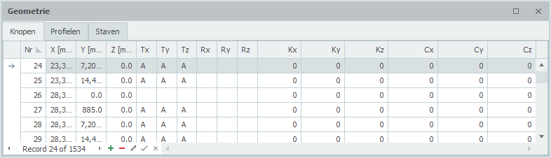
De tabellen voor Geometrie (Stramienlijnen/niveaus, Knopen, Profielen en Staven) en tabellen voor de Belastingen (Belastingsgevallen, Staafbelastingen, Knoopbelastingen en Combinaties) kunnen wel of niet in beeld worden gebracht.
Je kunt jouw constructie volledig grafisch invoeren waarbij het gebruik van tabellen niet echt nodig is. Toch kan het handig zijn om de gegevens zoals bijvoorbeeld knoopcoördinaten tabellarisch in beeld te zien. Dat kan. Maar in tegenstelling tot veel andere programma's kun je in die tabellen ook alle wijzigingen doen. Het maakt niet uit. Grafisch tekenen of numerieke invoer via tabellen kan gelijktijdig. Na elke wijziging worden alle tabellen bijgewerkt en de constructie opnieuw getekend. En vanzelfsprekend werken de undo en redo functies.
De schermen kunnen als 'floating' (dus op willekeurige positie in maar ook buiten het scherm) worden geplaatst, of worden 'ge-docked' links/rechts/boven/onder in het hoofdscherm. Dit geeft veel vrijheid. Je stelt zelf in wat je prettig vindt. Het programma onthoudt deze instelling zodat je dat maar één keer hoeft te doen. Vanzelfsprekend kun je dat altijd wijzigen.
Zo kan bijvoorbeeld bij toepassing van 2 computerschermen in het ene scherm de constructie grafisch full screen worden weergegeven en in het ander scherm de tabellen.
Changing Dimensions
Function: Modify dimensional properties of elements. Operation: Edit and update dimensions of structural elements including lengths, heights, and spacing.
Algemeen
Geometrie
Geometrie

Staven, Knopen, Platen, Opleggingen, Lokaal assenstelsel, Scharnier in staaf, Buitenschillen
Gerelateerde onderwerpen
Staven / Starre Verbindingen
Staven / Starre verbindingen
In het grafische scherm kunnen staven eenvoudig worden toegevoegd door de staven te tekenen. Kies in de functiebalk voor 
Staven worden als een "polylijn" getekend. Precies zoals dat o.a. ook in AutoCAD gebeurt. De beginknoop van een volgende staaf is de eindknoop van de laatst getekende staaf.
Het kan wel maar je hoeft niet eerst knopen te tekenen. Bij het tekenen van de staven worden ook knopen aangemaakt en toegevoegd.
Bij de eerste staaf verschijnt onderstaande dialoogvenster waar je o.a. de staafaansluitingen en het profiel kunt instellen. Gebruik de esc-toets of de rechter muisknop om het tekenen van staven te beëindigen.
Terwijl je tekent verschijnen ook hulplijnen (horizontaal en verticaal) naar eerder ingevoerde knopen. Vaak is het zo dat de knoop die je wilt toevoegen dezelfde x-, y- of z-maat heeft. Je kunt op die manier snel knopen plaatsen. Vanzelfsprekend kun je de coördinaten ook achteraf altijd aanpassen, getalsmatig of door verplaatsen.
Terwijl je tekent verschijnt parallel aan de staaflijn een maatlijn in één van de hoofdrichtingen x, y of z. Je kunt vrijwel net als in AutoCad de afstanden direct ook getalsmatig invoeren door gelijk het getal / de getallen in te typen vanaf jouw toetsenbord. Er zijn 3 mogelijkheden.
1. Tekenen van een staaf met een bekende afstand in één van de hoofdrichtingen
Het getal verschijnt in de maatlijn. Met de enter-toets wordt de invoer afgesloten en de staaf met die afstand toegevoegd.
2. Tekenen van een staaf met relatieve cartesische coördinaten (dx, dy, dz)
Eerst voer je de afstand in x-richting in. Het getal verschijnt in de maatlijn. Vervolgens typ je een punt-comma ";" in en de afstand in y-richting. Het getal verschijnt in een 2de invoerveld. Vervolgens typ je een punt-comma ";" in en de afstand in z-richting. Het getal verschijnt in een 3de invoerveld. Met de enter-toets wordt de invoer afgesloten en de staaf toegevoegd.
3. Invoer van relatieve cartesische coördinaten (dx, dy, dz) of absolute cartesische coördinaten (x, y, z)
Druk op de spatiebalk en het onderstaande dialoogvenster verschijnt. Hierin kun je relatieve coördinaten of absolute coördinaten direct invoeren.
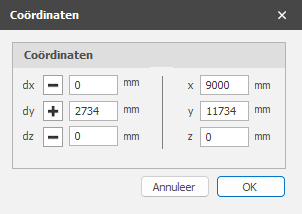
Op die manier kun je razendsnel jouw constructie in één keer invoeren.
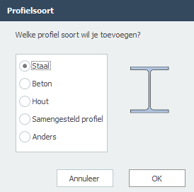
Profielselectie
De eerste keer wanneer je een staaf tekent, moet een profiel worden gekozen / aangemaakt. Er wordt gevraagd welk profielsoort je wilt invoeren. Ook als je een nieuw profiel invoert, wordt gevraagd welk profielsoort je wilt invoeren.
Vervolgens verschijnt het dialoogvenster van de profielen. Zie Profielen
Wijzigen van een staaf
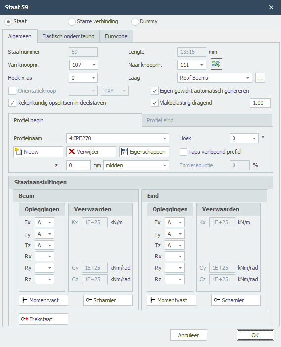
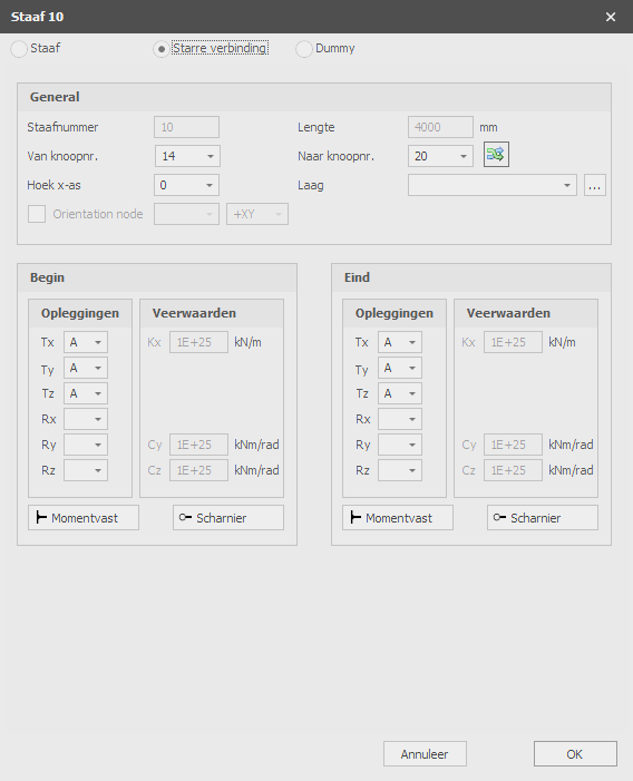
Wijziging van een staaf kun je door met de linker muisknop op de staaf te klikken en vervolgens met de rechter muisknop te kiezen voor eigenschappen. Of nog makkelijker door te dubbel klikken op de staaf. Het onderstaande dialoogvenster wordt geopend.
Gerelateerde onderwerpen
Staafgegevens
Staafnummer
Dit is het nummer van de staaf..
Lengte
De lengte van de staaf in mm.
Van knoopnr.
Het nummer van de beginknoop
Naar knoopnr.
Het nummer van de eindknoop
Balkoriëntatie omklappen

Met deze functie kun je de staaforiëntatie omdraaien. De begin- en eindknoop worden daarbij omgewisseld.
Hoek x-as
De hoek in graden waarmee je het lokale assenstelsel om de x-as kunt roteren. De klokrichting is positief.
Groep/Laag
Staven kunnen optioneel in lagen worden getekend, Dit komt overeen met de functionaliteit zoals in AutoCAD. Lagen kunnen zichtbaar of onzichtbaar worden ingesteld. (aan/uit) De namen van de lagen kun je aanpassen. Zie Weergaveopties
Oriëntatieknoop
Het nummer van de oriëntatieknoop. Dit is een knoop liggend in het lokale x-y vlak of x-z vlak.
Rekenkundig opsplitsen in deelstaven
Instelling of de staaf voor de bepaling van de krachtsverdeling (raamwerk berekening) rekenkundig moet worden gesplitst in deelstaven wanneer er knopen op de staaf worden gevonden. Standaard staat deze instelling aan.
Eigen gewicht automatisch genereren
Instelling of voor de staaf het eigen gewicht moet worden gegenereerd. Standaard staat deze instelling aan. Zie Berekeninginstellingen
Vlakbelasting dragend
Instelling of de staaf vlakbelasting dragend is of niet. Ook een correctiefactor waarmee de gegenereerde staafbelastingen uit de vlakbelastingen worden vergroot resp. verkleind om zo de statisch onbepaaldheid van de opgelegde plaat in rekening te brengen. Zie Vlakbelasting.
Profielnaam begin/eind
Hier kies je het profiel.
Hoek
De hoek van het profiel. Dat is de hoek t.o.v. het lokale assenstelsel. Normaal is dat 0 graden. Wanneer je bijvoorbeeld een kolom gedraaid wilt invoeren (dus belast over zijn zwakke as) voer je hier 90 graden in.
Profielbeheer
Je kunt nieuwe profielen aanmaken/toevoegen en verwijderen. Kies voor Eigenschappen wanneer je de profielgegevens wilt wijzigen en/of een ander standaard profiel wilt selecteren uit de profielen database.
Bij een nieuw profiel, wordt gevraagd welk profielsoort je wilt invoeren.
Taps verlopend profiel
Je kunt eventueel een taps verlopend profiel invoeren. Het tabblad "Profielnaam eind" wordt geactiveerd. Hier kun je het 2de profiel aan het einde van de staaf invoeren. Let op! De basisvorm van het profiel (H-, U-, L-vorm, enz.) moet wel overeenkomen met die van het profiel aan het begin van de staaf.
Voor berekeningsachtergrond. Zie Taps verlopend
z
Hiermee kan het profiel worden georiënteerd t.o.v. de schemalijn (De schemalijn is de lijn van begin- naar eindknoop)
z is de afstand in lokale z-richting tussen de schemalijn en de referentielijn van het profiel. De referentielijn van het profiel is standaard midden, maar kan worden ingesteld op bovenkant, midden of onderkant.
Torsiereductie
Percentage waarmee de wringstijfheid van de balk wordt verkleind. Specifiek voor betonnen balkroosters is in het geval van compatibiliteitswringing toegestaan om de wringstijfheid te verlagen. Het optredend wringend moment zal daardoor lager worden, en zal er minder snel wringwapening (beugels + langswapening) nodig zijn. Zie ook Compatibiliteitswringing.
Staafaansluitingen begin en eind
Hier voer je in hoe de staaf wordt aangesloten aan de begin- en eindknoop. Er zijn zeer veel mogelijkheden.
Je kunt gebruik maken van de meest gebruikte / standaard aansluitingen:
Momentvast
Tx=A(Absolute), Ty=A, Tz=A, Rx=A, Ry=A, Rz=A. (Dat is de standaard instelling)
Scharnierend
Tx=A, Ty=A, Tz=A. Er kunnen geen momenten worden overgedragen, alleen maar dwarskrachten en normaalkracht.
Trekstaaf
Als scharnierend met het verschil dat alleen trekkrachten (positieve normaalkrachten) kunnen worden overgedragen.
Verende aansluiting
Ook kun je een staaf verend aansluiten. Tx=S(Spring), Ry=S en/of Rz=S. Je geeft daarbij ook de veerwaarde Kx, Cy en/of Cz op in kN/m resp. kNm/rad.
Invoer per staaf
Dit geeft je de mogelijkheid om de invoer voor elke nieuwe staaf te wijzigen.
Gerelateerde onderwerpen
Eurocode
EN 1993-1-1 / EN 1995-1-1
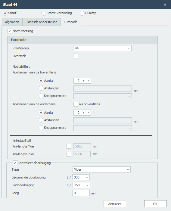
Specifiek en alleen voor de toetsing volgens Eurocode 3: NEN-EN 1993-1-1 resp. Eurocode 5: NEN-EN 1995-1-1 kunnen gegevens worden ingevoerd.
Staafgroep
Specifiek en alleen voor de toetsing van de kipstabiliteit kan een staafgroep worden ingevoerd. XFEM4U detecteert automatisch welke staven hiervoor in aanmerking komen. Alleen die staven die momentvast verbonden zijn aan deze staaf liggen en hetzelfde profiel hebben worden zichtbaar. Je kunt aanvinken welke staven dat zijn. Voor deze groep voer je vervolgens de kipafstanden in en eventueel de kniklengten.
Kipstabiliteit
Aantal kipsteunen / Afstanden kipsteunen
Alleen relevant voor de toetsing van de kipstabiliteit. Je kunt de kipsteunen voor de bovenflens en onderflens invoeren.
Er zijn 3 mogelijkheden.
-
Aantal: het aantal kipsteunen. Dat zijn de extra (kipsteunen) tussen de opleggingen verdeeld over de lengte van de staaf(groep).
-
Afstanden: afstanden van de kipsteunen gerekend vanaf het begin van de staaf(groep). De syntax is: "afstand1 afstand2 aantalxafstand3 ..enz" Voorbeeld: 3000 3x2200 2800
-
Knoopnummers: Het selecteren van de knoopnummers die op de staafgroep liggen.
Kniklengten Y-as en Z-as
De toetsing volgens Eurocode 3: EN 1993-1-1 is gebaseerd op een geometrisch niet lineaire krachtsverdeling. Zie ook Knik. Dat betekent dat knik van de staven in het vlak van het raamwerken impliciet is voorzien in de krachtsverdeling. Per belastingcombinatie wordt iteratief inwendig evenwicht bepaald.
Default wordt de kniklengte om de Y-as (sterke as) gelijk genomen aan de staaflengte. De kniklengte om de Z-as wordt gelijk genomen aan de grootste kipafstand. Je kunt voor beide kniklengten andere waarden invoeren. Zie ook Knik.
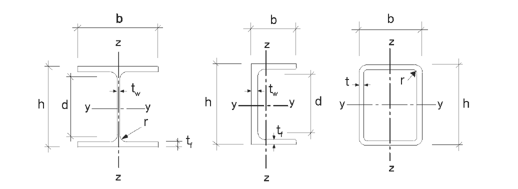
Opmerking: Onafhankelijk of het profiel t.o.v. het lokale assenstelsel is gedraaid, is Y-as de sterke as en de Z-as de zwakke as analoog aan de Eurocode. (Zie onderstaande.) In de toetsing worden alle staafkrachten getransformeerd naar dit assenstelsel.
Controleer doorbuiging
Instelling of de doorbuiging moet worden gecontroleerd.
Type
Type constructie. Dit bepaalt de eis van de bijkomende doorbuiging.
Bijkomende doorbuiging
Eis van de bijkomende doorbuiging.
Einddoorbuiging
Eis van de einddoorbuiging.
Zeeg
De grootte van de zeeg in mm.
Gerelateerde onderwerpen
Starre verbinding
Een starre verbinding is een element tussen 2 knooppunten met een bepaalde buigstijfheid en axiale stijfheid.
Volledig vast
Tx=A(Absolute), Ty=A, Tz=A, Rx=A, Ry=A, Rz=A.
Scharnierend
Tx=A, Ty=A, Tz=A. Er worden geen momenten overgedragen. Alleen dwarskrachten en normaalkrachten (Dit is de standaard instelling)
Alleen trek / Alleen druk
TX=P. Alleen trekkrachten (positieve normaalkrachten) kunnen worden overgedragen.
TX=N. Alleen drukkrachten (negatieve normaalkrachten) kunnen worden overgedragen.
Verende verbinding
Je kunt een starre verbinding ook met een veer aansluiten. Tx=S(Spring), Ry=S en/of Rz=S. Je moet dan de veerwaarde Kx, Cy en/of Cz in kN/m resp. kNm/rad opgegeven.
Gerelateerde onderwerpen
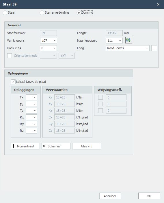
Dummy staaf
Specifiek voor platen en schijven is het mogelijk om dummy staven in te voeren. Rekenkundig wordt een dummy staaf in rekening gebracht met kleine buigstijfheden.
Lijnlasten: Met dummy staven kunnen willekeurige lijnlasten op een plaat in rekening worden gebracht.
Lijnvormige ondersteuningen: Dummy staven kunnen worden ondersteund.
Staafnummer
Dit is het nummer van de staaf..
Lengte
De lengte van de staaf in mm.
Van knoopnr.
Het nummer van de beginknoop
Naar knoopnr.
Het nummer van de eindknoop
Balkoriëntatie omklappen
Met deze functie kun je de staaforiëntatie omdraaien. De begin- en eindknoop worden daarbij omgewisseld.
Hoek x-as
De hoek in graden waarmee je het lokale assenstelsel om de x-as kunt roteren. De klokrichting is positief.
Groep/Laag
Staven kunnen optioneel in lagen worden getekend, Dit komt overeen met de functionaliteit zoals in AutoCAD. Lagen kunnen zichtbaar of onzichtbaar worden ingesteld. (aan/uit) De namen van de lagen kun je aanpassen. Zie Weergaveopties
Oriëntatieknoop
Het nummer van de oriëntatieknoop. Dit is een knoop liggend in het lokale x-y vlak of x-z vlak.
Opleggingen / Lijnvormige ondersteuningen
| aanduiding | omschrijving |
|---|---|
| ' ' | vrij - geen beperking |
| 'A' | volledig beperkt (Absolute) |
| 'P' | beperkt voor Positieve reactiekracht; vrij voor negatieve reactiekracht; veerwaarde kan worden ingevoerd. |
| 'N' | beperkt voor Negatieve reactiekracht; vrij voor positieve reactiekracht; veerwaarde kan worden ingevoerd. |
| 'S' | verend (Spring); veerwaarde moet worden ingevoerd. |
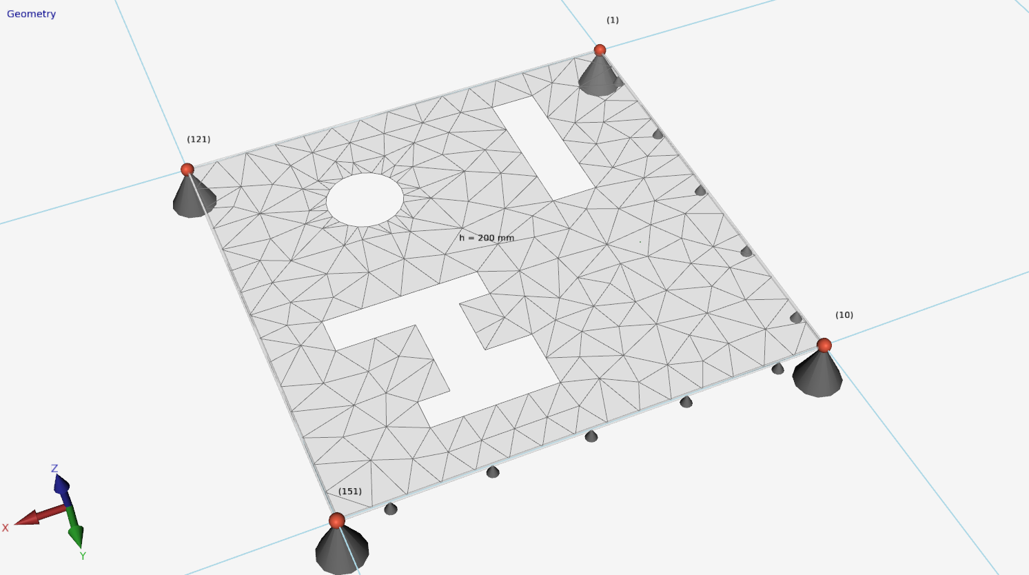
Lokaal t.o.v. de plaat
Instelling of de opleggingen t.o.v. het lokale assenstelsel van de plaat moet worden ingevoerd.
Opleggingen
Hier voer je in hoe de plaatrand wordt ondersteund. Er zijn zeer veel mogelijkheden.
Je kunt gebruik maken van de meest gebruikte / standaard opleggingen:
Momentvast: Tx=A(Absolute), Ty=A, Tz=A, Rx=A, Ry=A, Rz=A.
Scharnierend: Tx=A, Ty=A, Tz=A. Er kunnen geen momenten worden overgedragen, alleen maar dwarskrachten en normaalkracht.
Verende oplegging
Ook kun je een plaat verend ondersteunen. Tx=S(Spring), Ry=S en/of Rz=S. Je geeft daarbij ook de veerwaarde Kx, Cy en/of Cz op in kN/m resp. kNm/rad.
Lokale X-as
Invoer per staaf
Dit geeft je de mogelijkheid om de invoer voor elke nieuwe staaf te wijzigen.
Gerelateerde onderwerpen
Knooppunten
Knopen
Knopen kunnen in het grafische scherm eenvoudig worden toegevoegd. Kies in de menubalk voor  In deze modus kun je meerdere knopen met behulp van de linker muisknop toevoegen. Bij plaatsing zie je rechtsonder in beeld de coördinaten.

Knopen kunnen willekeurig worden geplaatst, in een vast raster, of op stramienlijnen.
Opleggingen zijn knopen die in een bepaalde richting worden vastgezet.
Wijzigen van een knoop
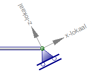
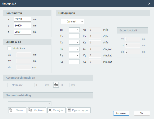
Wijziging van een knoop kun je door met de linker muisknop op de knoop te klikken en vervolgens met de rechter muisknop te kiezen voor eigenschappen. Of nog makkelijker door te dubbel klikken op de knoop. Het onderstaande dialoogvenster wordt geopend
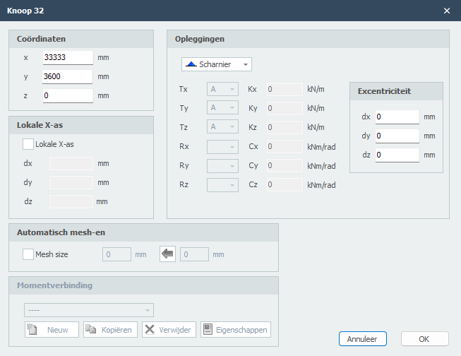
Coördinaten
x
x-coördinaat
y
y-coördinaat
z
z-coördinaat
Lokale X-as
Opleggingen
Zie Opleggingen
Je kunt kiezen uit de opleggingen die vaak in de praktijk voorkomen maar Je kunt ook zelf een willekeurige (verende) oplegging maken door gebruik te maken van 'A','P','N' of 'S'.
Excentriciteiten
Alleen voor opleggingen (Dat zijn knopen met een beperkingen / restraints in een bepaald richting) kun je een excentriciteit invoeren door 3 relatieve coördinaten dx, dy en dz in te voeren. Er worden automatisch een extra knoop en "stijve" staaf gegenereerd. Hiermee kun je bijvoorbeeld in de berekening van een balkrooster beton een misplaatsing van een paal eenvoudig in rekening brengen. De funderingsstaven kunnen vervolgens op wringing en extra buiging worden getoetst.
Mesh
Zie Mesh
Momentverbinding
Zie Verbindingen
Tabel Knopen
Knopen kunnen ook in de tabel Knopen worden toegevoegd en/of gewijzigd. Het maakt niet uit. Ook kun je tussentijds wisselen tussen grafische invoer en tabellarische invoer.
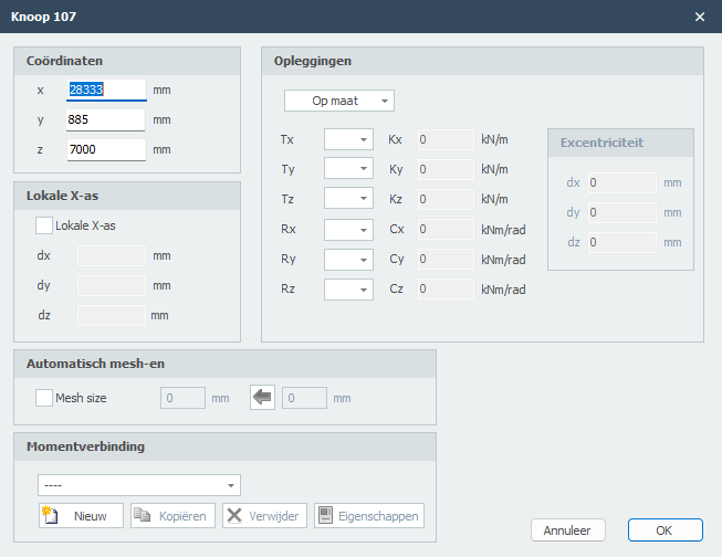
Lokaal knoop-assenstelsel
In elke knoop kan een (knoop-)assenstelsel worden toegepast.

voorbeeld van een rol-oplegging onder een hoek.
Lokale X-as
De oorsprong ligt in de betreffende knoop. De richting van de X-as wordt beschreven met 3 relatieve coördinaten. (zie bovenstaande figuur). Lokale assenstelsels kunnen worden gebruikt om knoopbeperkingen (opleggingen of 'restrains'), maar ook om knoopbelastingen en/of knoopverplaatsingen in een willekeurige richting op te geven.
Opleggingen
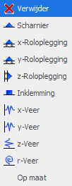
Standaard opleggingen kunnen in het grafische scherm eenvoudig worden toegevoegd. Kies in de menubalk voor één van de onderstaande opleggingen.
Opmerking:
Dit zijn de opleggingen die vaak in de praktijk voorkomen maar Je kunt ook zelf een willekeurige (verende) oplegging maken door gebruik te maken van 'A','P','N' of 'S'. Zie de onderstaande tabel.
Standaard opleggingen
 scharnier (Tz,Ty,Rz) ('A','A',' ')
 roloplegging z-richting (Tx,Tz,Ry) (' ','A',' ')
 roloplegging x-richting (Tx,Tz,Ry) ('A',' ',' ')
 volledige inklemming (Tx,Tz,Ry) ('A','A','A')
 verende oplegging x-richting (Tx,Tz,Ry) ('S',' ',' ')
 verende oplegging z-richting (Tx,Tz,Ry) (' ','S',' ')
 verende oplegging om y-as (Tx,Tz,Ry) (' ',' ','S')
Opleggingen kunnen willekeurig worden geplaatst, in een vast raster, of op stramienlijnen.
Opleggingen zijn knopen die in een bepaalde richting worden vastgezet.
Wijzigen van een oplegging
Wijziging van een oplegging kun je door met de linker muisknop op de knoop te klikken en vervolgens met de rechter muisknop te kiezen voor eigenschappen. Of nog makkelijker door te dubbel klikken op de knoop. Het onderstaande dialoogvenster wordt geopend.
Oplegging aanduidingen
| aanduiding | omschrijving |
|---|---|
| ' ' | vrij - geen beperking |
| 'A' | volledig beperkt (Absolute) |
| 'P' | beperkt voor Positieve reactiekracht; vrij voor negatieve reactiekracht; veerwaarde kan worden ingevoerd. |
| 'N' | beperkt voor Negatieve reactiekracht; vrij voor positieve reactiekracht; veerwaarde kan worden ingevoerd. |
| 'S' | verend (Spring); veerwaarde moet worden ingevoerd. |
Tabel Knopen
Opleggingen kunnen ook in de tabel Knopen linksonder worden toegevoegd en/of gewijzigd. Het maakt niet uit. Ook kun je tussentijds wisselen tussen grafische invoer en tabellarische invoer.
Mesh
Mesh size
De afmeting van de gegenereerde plaatelementen. De standaard (aanbevolen) mesh size wordt automatisch bepaald maar kan per knoop worden aangepast.
Knoopverbindingen
Je kunt per knoop een nieuwe verbinding toevoegen. Wanneer je de verbinding hebt toegevoegd kun je ook dezelfde verbinding in andere knopen toepassen.

Je kunt nieuwe verbindingen maken/toevoegen, verbindingen kopiëren en verwijderen. Kies Eigenschappen wanneer je de verbinding wilt wijzigen.
Zie Verbindingen voor meer details.
Profielen
Profielen
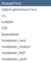
De eerste keer wanneer je een staaf tekent, moet een profiel worden gekozen / aangemaakt. Er wordt gevraagd welk profielsoort je wilt invoeren. Ook als je een nieuw profiel invoert, wordt gevraagd welk profielsoort je wilt invoeren.
Afhankelijk van jouw keuze verschijnen de onderstaande dialoogvensters.
Profieltypes
Materiaalgebaseerde Profielen
Speciale Profielen
- Samengestelde Doorsnede - Aangepaste samengestelde secties
- Grafische Invoer
- Invoer
Beton-Specifieke Instellingen
- Kruip - Kruip- en krimpeigenschappen
- Blootstellingsklassen - Milieu blootstellingsclassificaties
Staal
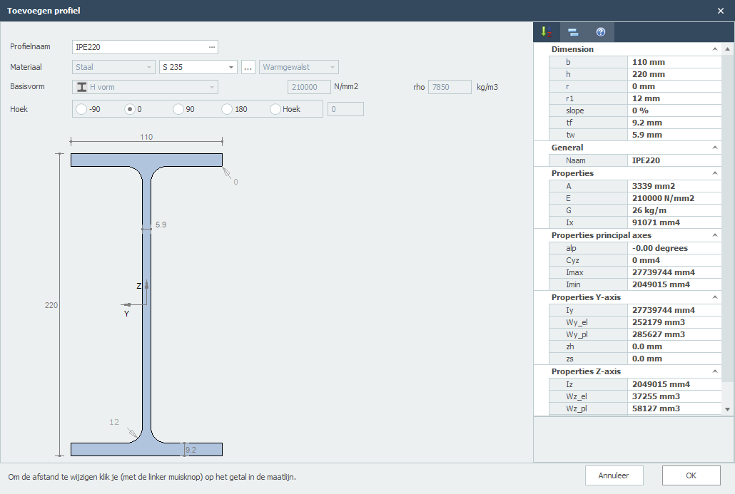
Opmerking: Je kunt de profielafmetingen wijzigen door op de betreffende getallen in de maatlijnen te klikken.
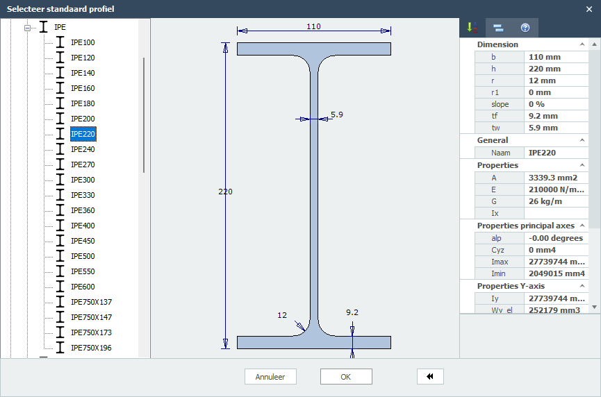
Profielnaam
Voer hier de profielnaam in of selecteer uit het profielen databestand. Je kunt hier dus ook gelijk IPE160, HEA200 of HE200A intypen.
Wil je een staalprofiel selecteren uit de database, klik op de de 3 puntjes ... aan de rechterkant in het invoerveld.
Materiaal
Staal
Staalsoort
Keuze uit S235, S275 en S355.
Procede
Keuze uit warmgewalst, koudgevormd of gelast.
Basisvorm
Je kunt kiezen uit een aantal basisvormen zodat je zelf jouw profiel kunt samenstellen.
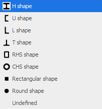
Nadat je een basisvorm hebt geselecteerd kun je vervolgens alle profielafmetingen wijzigen door op de betreffende getallen in de maatlijnen te klikken. Je kunt ook de profielafmetingen van de standaard profielen op die manier aanpassen.
E
De elasticiteitsmodulus kun je wijzigen.
Hoek
Het profiel kun je over een hoek draaien.
Gerelateerde Onderwerpen
Beton
Beton
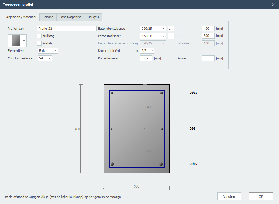
Doorsnedevorm
Je kunt kiezen uit een groot aantal doorsnedevormen. Wanneer een vorm hebt gekozen, kun je vervolgens de profielafmetingen aanpassen door op de betreffende getallen in de maatlijnen te klikken.
Druklaag
Instelling of een druklaag met een andere betonsterkteklasse wilt toepassen.
Prefab
Instelling of een druklaag met een andere betonsterkteklasse wilt toepassen.
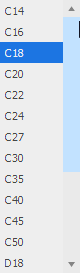
Betonsterkteklasse
De betonsterkteklasse.
Betonstaalsoort
Betonstaalsoort van de langs- en dwarkrachtwapening.
Kruipcoëfficiënt
De kruipcoëfficiënt van beton. Met deze coëfficiënt wordt de effectieve kruipcoëfficiënt berekend volgens EN 1992-1-1 art. 5.8.4.
Je kunt de kruipcoëfficiënt zelf opgeven of laten berekenen. Zie Kruip. Wanneer je de kruipcoëfficiënt laat berekenen wordt een gedetailleerde berekening volgens EN 1992-1-1 B.1 in de uitvoer weergegeven.
Korreldiameter
De nominale korreldiameter beton.
Hoogte betondoorsnede in mm.
b
Breedte betondoorsnede in mm.
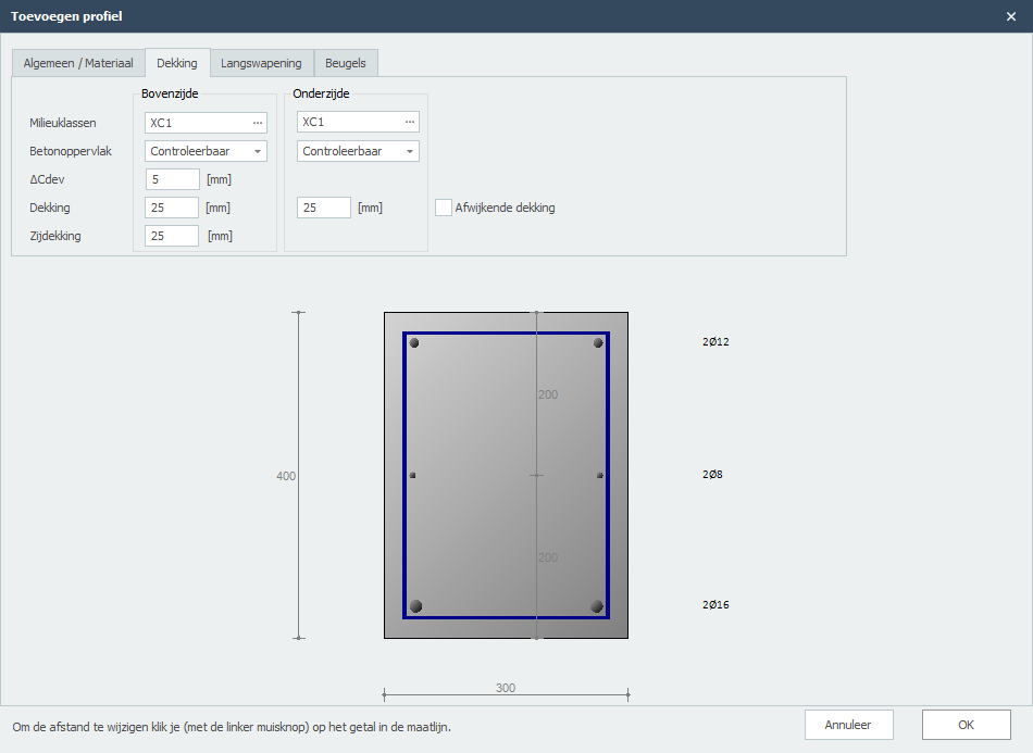
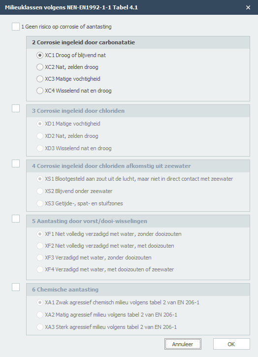
Milieuklasse
De milieuklasse wordt o.a. gebruikt voor de bepaling van de benodigde dekking. Zie Milieuklasse(n)
Betonoppervlak
Controleerbaar, oncontroleerbaar of nabewerkt.
delta_Cdev
Uitvoeringstolerantie op de betondekking in mm.
Dekking
Betondekking boven/onder in mm.
Zijdekking
Zijdekking links/rechts in mm.
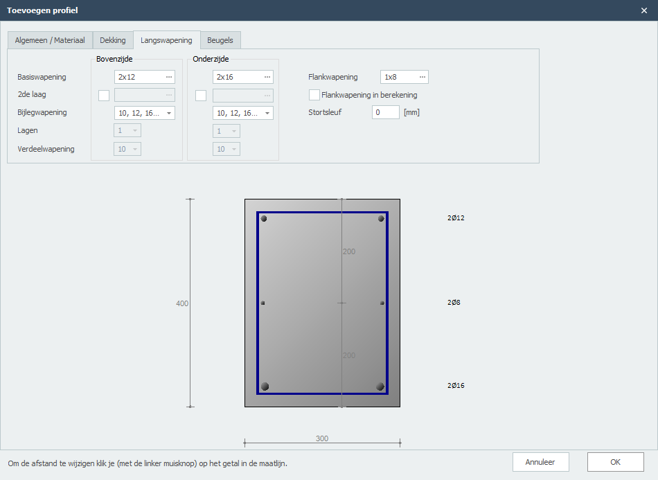
Flankwapening
Dit is de flankwapening per zijde (links en rechts). Je kunt ook de afstanden aanpassen.
Flankwapening in berekening
De flankwapening wordt ook meegenomen in de berekening van het opneembaar moment. De gebruiker kan zelf instellen of die flankwapening moet worden meegenomen in de berekening of niet. Standaard staat dat uit.
Stortsleuf
Stortsleuf in mm.
Diameters
Beugeldiameters.
Afstanden
Beugelafstanden.
Aantal beugelsneden
Het aantal beugelsneden. Voor dwarskracht is dat normaalgesproken 2.
Hoek betondrukdiagonaal
Hoek betondrukdiagonaal in graden.
Minimale dwarskrachwapening
Instelling of rekening moet worden gehouden met de minimale dwarskrachtwapening.
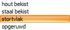
Type stortvlak
In het geval van een druklaag kan hier het stortvlak worden ingevoerd.
h (dwarskracht)
Hoogte betondoorsnede voor de dwarskrachtberekening in mm.
b (dwarskracht)
Breedte betondoorsnede voor de dwarskrachtberekening in mm.
Betonsterkteklasse (dwarskracht)
In het geval van een druklaag: Betonsterkteklasse die voor de dwarskrachtberekening moet worden gehanteerd.
Kruip
Kruipcoëfficiënt
In veel gevallen is het verstandig om de kruipcoëfficiënt nauwkeurig te berekenen. Over het algemeen zal de kruipcoëfficiënt en dus ook de effectieve kruipcoëfficiënt lager zijn.
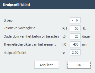
Cementklasse
De gekozen cementklasse.
Relatieve vochtigheid
De relatieve vochtigheid in %.
Ouderdom
De ouderdom van het element in dagen op het moment van belasten.
Theoretische dikte
De theoretische dikte van het element in mm.
Kruipcoëfficiënt (berekend)
De berekende kruipcoëfficiënt volgens EN 1992-1-1 B.1.
Gerelateerde Onderwerpen
Milieuklasse(n)
In veel gevallen is er sprake van meerdere milieuklassen. Hier kun je een of meer milieuklassen invoeren. XFEM4U bepaalt automatisch welke milieuklasse maatgevend is voor de bepaling van de minimaal benodigde betondekking.
Gerelateerde Onderwerpen
Hout
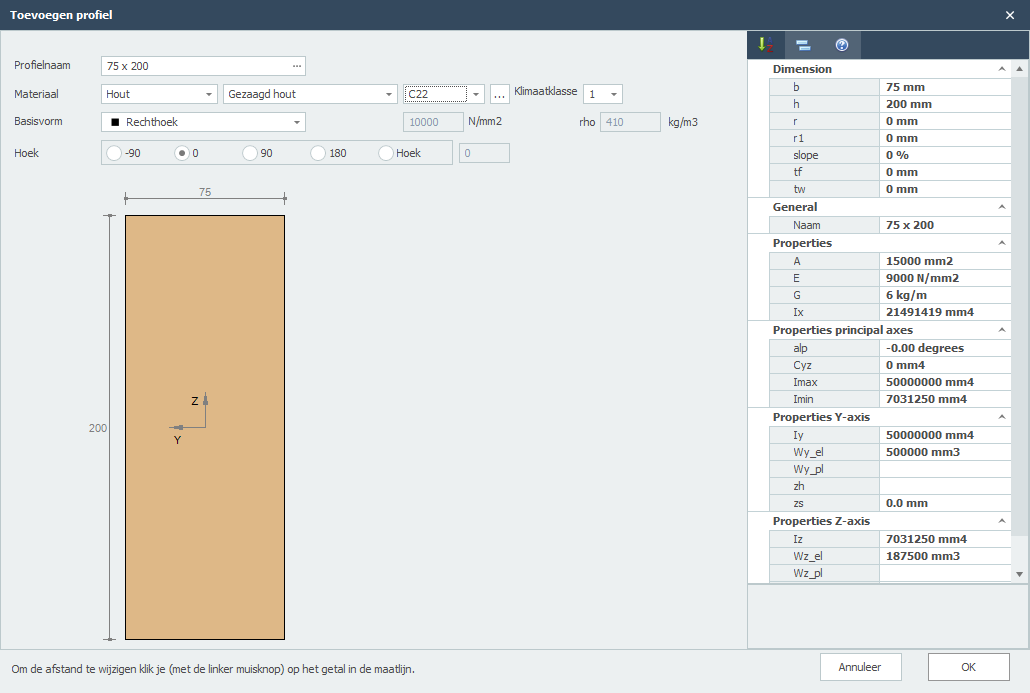
Opmerking: Je kunt de profielafmetingen wijzigen door op de betreffende getallen in de maatlijnen te klikken.
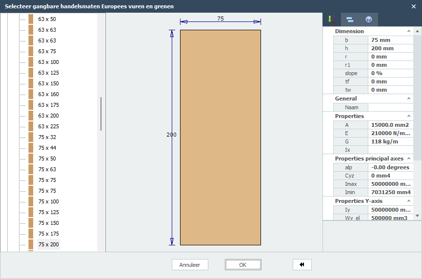
Profielnaam
Voer hier de profielnaam in of selecteer uit het profielen databestand. Je kunt hier dus ook gelijk 75 x 200 of 75 x 225 intypen.
Wilt een bekend staalprofiel selecteren uit de database, klik op de de 3 puntjes ... aan de rechterkant in het invoerveld.
Materiaal
Hout
Houtsoort
Houtklasse
Klimaatklasse

Basisvorm
Je kunt kiezen uit een aantal basisvormen zodat je zelf jouw profiel kunt samenstellen.
Nadat je een basisvorm hebt geselecteerd kun je vervolgens alle profielafmetingen wijzigen door op de beterffende getallen in de maatlijnen te klikken. Je kunt ook de profielafmetingen van de standaard profielen op die manier aanpassen.
E
De elasticiteitsmodulus kun je wijzigen.
Hoek
Het profiel kun je over een draaien.
Gerelateerde Onderwerpen
Samengestelde doorsnede
Samengesteld profiel
Met behulp van deze module kun je elke profiel samenstellen.
Invoer
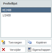
Hier kun je profielen Toevoegen, Kopiëren en Verwijderen. Met Eigenschappen kun je een ander profiel kiezen of de profielafmetingen aanpassen.
Profielnaam
Voer hier de profielnaam in of selecteer uit het profielen databestand.
Speciale invoer
1) Gehalveerde H syntax: "1/2 profielnaam [ - minmaat ]"
Voorbeeld: 1/2IPE300 of 1/2HE650B-5
2) Rechthoek: syntax: "S breedte x hoogte" of "F breedte x hoogte"
Voorbeeld: S200x12
3) Gat: syntax: "G breedte x hoogte" of "H breedte x hoogte"
Voorbeeld: G50x25
4) Rond: syntax: "R diameter"
Voorbeeld: R50
5) Buis(segment): syntax: "R diameter x dikte [ / hoek1 / hoek2 ] "
Voorbeeld: R500x12 of R500x12/0/180
6) Driehoek: syntax: "D hoogte x breedte" of "T hoogte x breedte"
Voorbeeld: D50x60
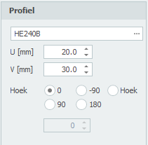
U
Coordinaat u in mm van het profiel.
V
Coordinaat v in mm van het profiel.
Hoek
Hoek in graden van het profiel.
Gerelateerde onderwerpen
Grafische invoer
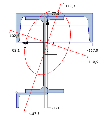
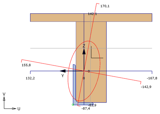
Een grafische weergave van de totale samengestelde doorsnede, met daarin standaard:
- de doorsneden van alle profielen waarbij het actieve profiel met een andere kleur wordt weergegeven.
- het assenstelsel
- de plaats van het zwaartepunt
- de hoofdtraagheidsassen
- afstanden vanuit het zwaartepunt naar de uiterste vezels
- weergave van de traagheidsstralen.
- weergave van de halveringslijnen
Rechtermuisklik contextmenu
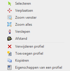
Menu

Selecteren
Je kunt in deze modus een profiel selecteren (actief maken). Werkwijze: Verplaatst de cursor binnen het contour van het profiel en druk op de linker muisknop.
Verplaatsen
Profielen kunnen eenvoudig grafisch worden verplaatst. Er wordt automatisch "ge-snapt" naar vaste / bekende punten waardoor het verplaatsen heel eenvoudig is. Ook kun je de coördinaten (U,V) nummeriek aanpassen.
Zoom venster
Deze functie wordt gebruikt om in te zoomen op een bepaald gedeelte in de doorsnedetekening. Werkwijze: Met de linker muisknop ingedrukt trek je een rechthoekig venster van linksonder naar rechtsboven. De modus wordt automatisch uitgeschakeld nadat is ingezoomd.
Zoom alles
Deze functie wordt gebruikt om alles te laten zien. De modus wordt automatisch uitgeschakeld wanneer is uitgezoomd.
Verslepen
Werkwijze: Met de linker muisknop ingedrukt kun je de tekening verslepen.
Afstand meten
In deze modus kunnen afstanden worden gemeten. Er wordt automatisch "ge-snapt" naar alle voorkomende contourpunten en punten in het midden van alle lijnstukken.
Gerelateerde onderwerpen
Vloeren / Platen
Platen
In het grafische scherm kunnen platen eenvoudig worden toegevoegd door de plaatranden te tekenen. Kies in de functiebalk voor 
De plaatranden worden als een "polylijn" getekend. Precies zoals dat o.a. ook in AutoCAD gebeurt. De beginknoop van een volgende plaatrand is de eindknoop van de laatst getekende plaatrand.
Het kan wel maar je hoeft niet eerst knopen te tekenen. Bij het tekenen van de plaatranden worden ook knopen aangemaakt en toegevoegd.
Bij de eerste plaatrand verschijnt onderstaande dialoogvenster (zie Plaatgegevens) waar je o.a. de materiaalgegevens kunt instellen. Gebruik de esc-toets of de rechter muisknop om het tekenen van de plaatranden te beëindigen.

Terwijl je tekent verschijnen ook hulplijnen (horizontaal en verticaal) naar eerder ingevoerde knopen. Vaak is het zo dat de knoop die je wilt toevoegen dezelfde x-, y- of z-maat heeft. Je kunt op die manier snel knopen plaatsen. Vanzelfsprekend kun je de coördinaten ook achteraf altijd aanpassen, getalsmatig of door verplaatsen.
Terwijl je tekent verschijnt parallel aan de plaatrand een maatlijn in één van de hoofdrichtingen x, y of z. Je kunt vrijwel net als in AutoCad de afstanden direct ook getalsmatig invoeren door gelijk het getal / de getallen in te typen vanaf jouw toetsenbord. Er zijn 3 mogelijkheden.
1. Tekenen van een plaatrand met een bekende afstand in één van de hoofdrichtingen.
Het getal verschijnt in de maatlijn. Met de enter-toets wordt de invoer afgesloten en de plaatrand met die afstand toegevoegd.
2. Tekenen van een plaatrand met relatieve cartesische coördinaten (dx, dy, dz).
Eerst voer je de afstand in x-richting in. Het getal verschijnt in de maatlijn. Vervolgens typ je een punt-comma ";" in en de afstand in y-richting. Het getal verschijnt in een 2de invoerveld. Vervolgens typ je een punt-comma ";" in en de afstand in z-richting. Het getal verschijnt in een 3de invoerveld. Met de enter-toets wordt de invoer afgesloten en de plaatrand toegevoegd.
3. Invoer van relatieve cartesische coördinaten (dx, dy, dz) of absolute cartesische coördinaten (x, y, z).
Druk op de spatiebalk en het onderstaande dialoogvenster verschijnt. Hierin kun je relatieve coördinaten of absolute coördinaten direct invoeren.
Op die manier kun je razendsnel jouw constructie in één keer invoeren.
Wanneer het tekenen van de plaatranden wordt beëindigd, wordt de plaat automatisch ge-mesh-t met de aanbevolen/default mesh size.
Lokaal assenstelsel
De x-as van het lokale assenstelsel van de plaat loopt van het eerste punt naar het tweede punt. Met de weergave optie Assenstelsel plaat kun je het lokale assenstelsel van de plaat zichtbaar maken. Zie Weergaveopties.

Met deze functie kun je de richting van de contourlijn ("polylijn") omdraaien. Daarmee beïnvloedt je dus ook het assenstelsel van de plaat.
Ondersteuning en belasting
De plaat kan op verschillende manier worden ondersteund. Door knopen en/of door randen.
Je kunt vlakbelastingen invoeren en/of knoopbelastingen.
Gerelateerde onderwerpen
Plaatgegevens
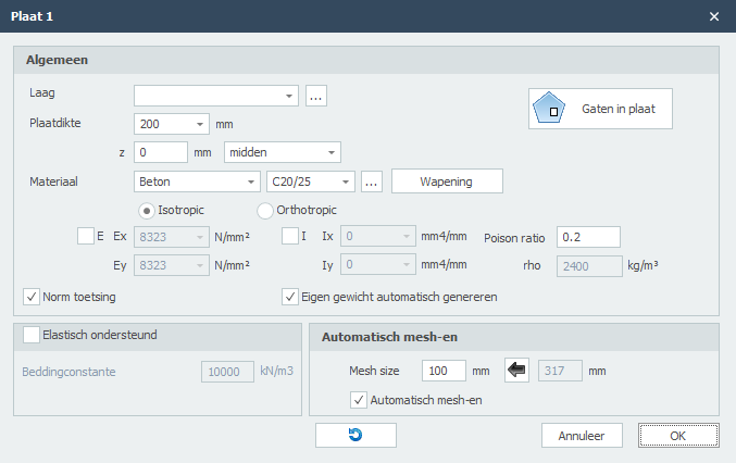
Door op een plaat te dubbelklikken (of 1 klik rechtermuisknop > Eigenschappen) wordt onderstaand dialoogvenster zichtbaar.
Groep/Laag
Staven kunnen optioneel in lagen worden getekend, Dit komt overeen met de functionaliteit zoals in AutoCAD. Lagen kunnen zichtbaar of onzichtbaar worden ingesteld. (aan/uit) De namen van de lagen kun je aanpassen. Zie Weergaveopties
Plaatdikte
De plaatdikte in mm.
z
Hiermee kan het plaat worden georiënteerd t.o.v. de schemavlak.
z is de afstand in lokale z-richting tussen het schemavlak en de referentielijn van de plaat. De referentielijn van de plaat is standaard midden, maar kan worden ingesteld op bovenkant, midden of onderkant.
Materiaal
Er kan worden gekozen uit staal, beton en hout. (en anders)
Afhankelijk van de keus wordt het dialoogvenster aangepast om de verschillende materiaalgegevens, zoals de kwaliteit kan worden ingevoerd.
Isotroop / Orthotroop
Standaard is de plaat isotroop waarbij de E en I om de x-as en y-as gelijk zijn. Je kunt de plaat ook orthotroop invoeren waarbij de E en I om de x-as en y-as ongelijk zijn.
Let op! De Ix resp Ex. betreft de stijfheid om de x-as. Het moment mxx is het moment is dat spanningen in de x-richting geeft. Dat geeft nog weleens verwarring.

Ex / Ey
Elasticiteitsmodulus in N/mm2. Deze waarde wordt automatisch bepaald maar kan worden aangepast.
Ix / Iy
Traagheidsmoment mm4. Deze waarde wordt automatisch bepaald maar kan worden aangepast.
Poison ratio
De poison ratio. Deze waarde wordt automatisch bepaald maar kan worden aangepast.
rho
Soortelijk gewicht in kg/m3. Deze waarde kan niet worden aangepast. Met deze waarde wordt automatisch het eigen gewicht gegenereerd.
Eigen gewicht automatisch genereren
Instelling of het eigen gewicht moet worden genereerd. De belasting a.g.v. het eigen gewicht wordt berekend met de zwaartekrachtversnelling (of valversnelling). Zie Berekeninginstellingen
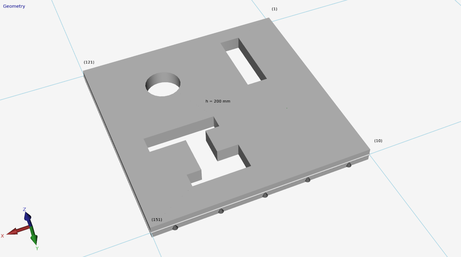
Gaten in plaat
Hiermee kun je gaten in de plaat invoeren. Zie Gaten in plaat.
Elastisch ondersteund
Dit geeft de mogelijkheid om de plaat elastisch te ondersteunen. De bedding wordt geschematiseerd als een reeks veren die alleen positieve reacties kunnen opnemen. Eventueel "loskomen" is dan ook voorzien. De beddingconstante wordt automatisch omgezet naar veren met de juiste veerwaarde.
Beddingsconstante
De beddingsconstante K in kN/m3. De default waarde is 10.000 kN/m3.
Globale waarden van de beddingsconstante K van diverse type ondergronden:
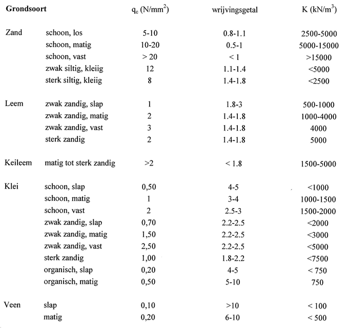
Mesh size
De afmeting van de gegenereerde plaatelementen. De standaard (aanbevolen) mesh size wordt automatisch bepaald maar kan worden aangepast.
Automatisch mesh-en
Bij het invoeren van een plaat of wand wordt de plaat resp. wand automatisch ge-mesh-t. Bij kleine modellen is dat zeker handig. Bij grote modellen niet. Het mesh-en van veel aansluitende platen kost relatief veel tijd. Je kunt automatisch mesh-en uitzetten. Dat kan bij de weergaveopties en hier in het dialoogvenster van de plaat. Je kunt nu nog makkelijker jouw platen invoeren. En ben je daar klaar mee dan kun je de platen in één keer mesh-en.
Mesh
Knop waarmee de mesh opnieuw wordt gegenereerd.
Lokaal assenstelsel
De x-as van het lokale assenstelsel van de plaat loopt van het eerste punt naar het tweede punt. Met de weergave optie Assenstelsel plaat kun je het lokale assenstelsel van de plaat zichtbaar maken. Zie Weergaveopties.
Met deze functie kun je de richting van de contourlijn ("polylijn") omdraaien. Daarmee beïnvloedt je dus ook het assenstelsel van de plaat.
Gerelateerde onderwerpen
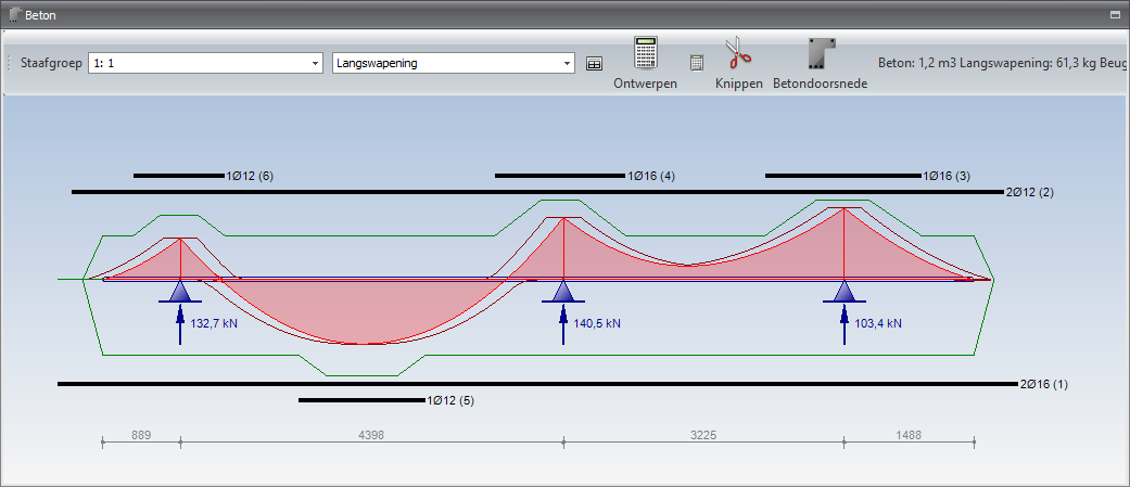
Langswapening
De langswapening wordt automatisch ontworpen. Op dit tabblad wordt de wapening getoond en kun je de wapening aanpassen. Zowel de basiswapening als de bijlegwapening.
Wapeningstaven aanpassen
Dubbelklik met de linkermuis op de wapening. Er wordt een dialogvenster geopend.

Je kunt kiezen uit "aantal x diameter", "diameter - hoh" of "mm2"
Wapeningstaven verlengen/verkorten
Ga met de muis naar het eind van de wapening. De cursor verandert en kun je de staaf eenvoudig verlengen of verkorten.
Wapeningstaven kopiëren
Plaats de muis op de wapening. Met rechtermuisknop open je een context menu. Kies voor kopieer.
Wapeningstaven verwijderen
Plaats de muis op de wapening. Met rechtermuisknop open je een context menu. Kies voor verwijder.
Menu
Staafgroep
Hier kun je de balk selecteren die je in beeld wilt brengen. Je kunt ook in de 3d weergave klikken op de balk. Deze wordt in geel weergegeven
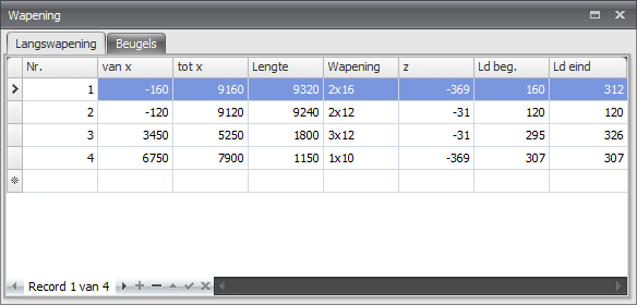
Langswapening / Beugels
Je kunt kiezen om de langswapening of de beugels in beeld te brengen.
Toon een verplaatsbaar scherm met wapening tabellen

Ontwerpen

Met deze functie kun je de wapening van deze balk opnieuw ontwerpen. Dat kan nodig zijn wanneer je bijvoorbeeld de geometrie of belasting hebt aangepast.
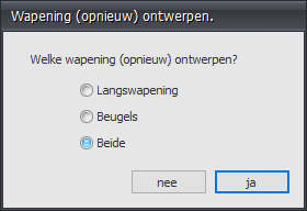
Ontwerpen van alle staven

Met deze functie kun je de wapening van alle staven opnieuw ontwerpen. Dat kan nodig zijn wanneer je bijvoorbeeld de geometrie of belasting hebt aangepast.
Knippen

Je kunt op de wapeningstaven knippen.
Betondoorsnede

Met deze functie kun je een gedetailleerde tekening en berekening opvragen van elke doorsnede.
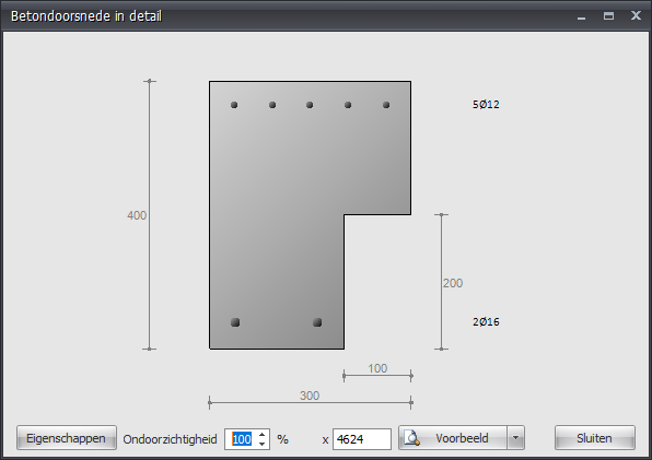
Kies voor Voorbeeld voor een gedetailleerde berekening.
Gerelateerde onderwerpen
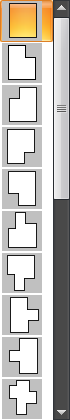
Gaten in plaat
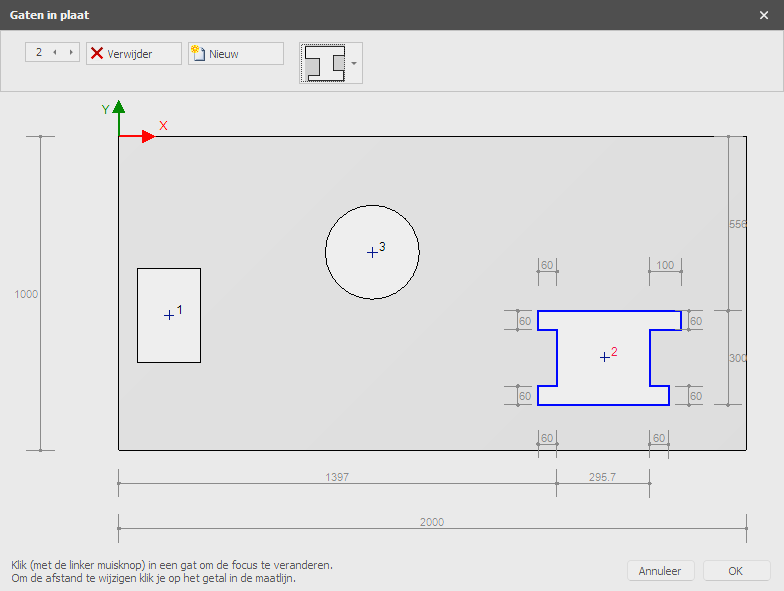
Hier kun je eenvoudig gaten invoeren. Er kan worden gekozen uit een groot aantal basisvormen die geparametiseerd zijn.
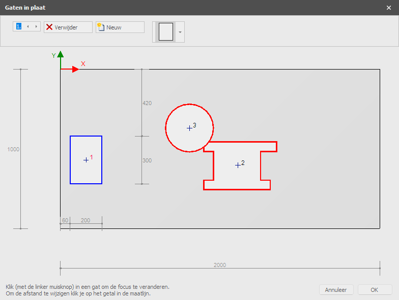
De positie en de afmetingen van het gat of opening kunnen worden aangepast door op de betreffende maatlijn te klikken. De focus in het geval van meerdere gaten kun je veranderen door met de linker muisknop in het gatcontour te klikken. Wanneer je de linker muisknop ingedrukt houdt en de muis nu verplaatst, verplaats je het gat grafisch.
Er wordt gecontroleerd of gaten elkaar overlappen of de buiten contour doorsnijden.
Gerelateerde onderwerpen
Plaatrand
Plaatranden worden als transparante buisjes getekend. Door op een plaatrand te dubbelklikken (of 1 klik rechtermuisknop > Eigenschappen) wordt onderstaand dialoogvenster zichtbaar.
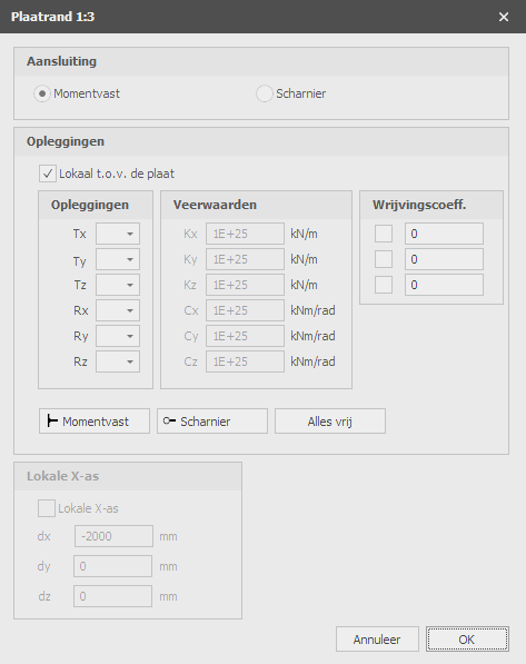
Aansluiting
Instelling of plaatrandelementen momentvast of scharnierend worden verbonden.
Lokaal t.o.v. de plaat
Instelling of de opleggingen t.o.v. het lokale assenstelsel van de plaat moet worden ingevoerd.
Opleggingen
Hier voer je in hoe de plaatrand wordt ondersteund. Er zijn zeer veel mogelijkheden.
| aanduiding | omschrijving |
|---|---|
| ' ' | vrij - geen beperking |
| 'A' | volledig beperkt (Absolute) |
| 'P' | beperkt voor Positieve reactiekracht; vrij voor negatieve reactiekracht; veerwaarde kan worden ingevoerd. |
| 'N' | beperkt voor Negatieve reactiekracht; vrij voor positieve reactiekracht; veerwaarde kan worden ingevoerd. |
| 'S' | verend (Spring); veerwaarde moet worden ingevoerd. |
Je kunt gebruik maken van de meest gebruikte / standaard opleggingen:
- Momentvast Tx=A(Absolute), Ty=A, Tz=A, Rx=A, Ry=A, Rz=A.
- Scharnierend Tx=A, Ty=A, Tz=A. Er kunnen geen momenten worden overgedragen, alleen maar dwarskrachten en normaalkracht.
Verende oplegging
Ook kun je een plaat verend ondersteunen. Tx=S(Spring), Ry=S en/of Rz=S. Je geeft daarbij ook de veerwaarde Kx, Cy en/of Cz op in kN/m resp. kNm/rad.
Lokale X-as
Gerelateerde onderwerpen
Verbindingen
Verbindingen per knoop
Per knoop kun je een nieuwe verbinding toevoegen. Wanneer je de verbinding hebt toegevoegd kun je dezelfde verbinding ook in andere knopen toepassen.


Je kunt nieuwe verbindingen aanmaken/toevoegen, verbindingen Kopiëren en verwijderen. Kies voor Eigenschappen wanneer je de verbinding wilt wijzigen.
Zie Verbindingen
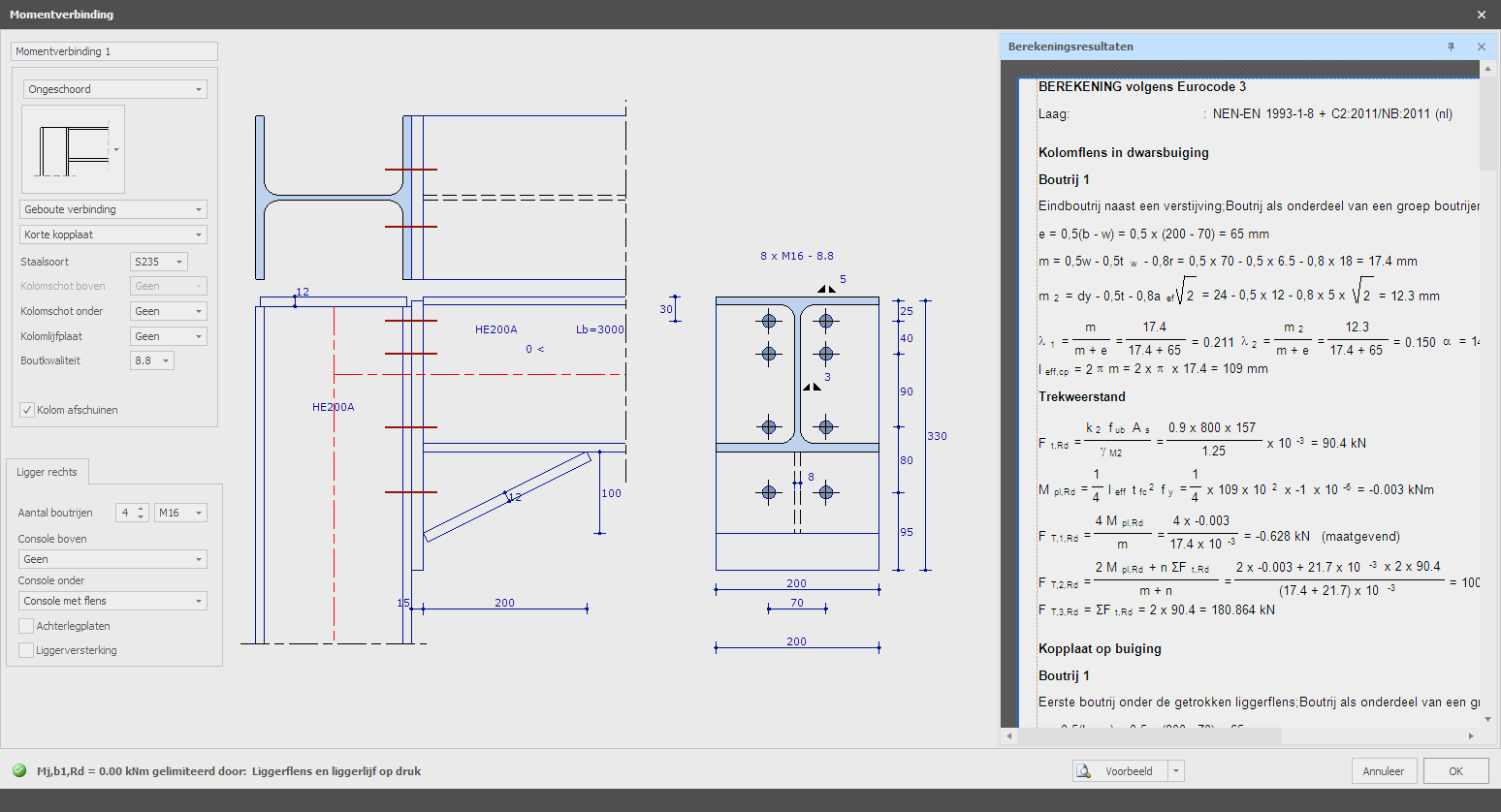
Berekening
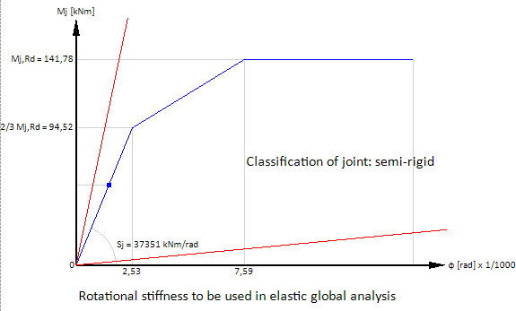
Belastingafhankelijke rotatiestijfheid
In XFEM4U wordt standaard een geometrisch niet-lineaire analyse (GNL) berekend. De krachtsverdeling wordt iteratief bepaald. De balk-kolom momentverbindingen kunnen worden ingevoerd. De rotatiestijfheid van alle verbindingen per iteratiestap wordt bepaald. Op basis van het optredende moment in de balkverbinding bepaalt het rotatiestijfheidsdiagram van de ontworpen verbinding (zie diagram hieronder) een rotatiestijfheid of veerstijfheid die vervolgens wordt gebruikt in de volgende iteratiestap. De iteratie stopt wanneer er geen veranderingen meer zijn in de krachtsverdeling.
In XFEM4U wordt daarom voor alle momentverbindingen een belastingafhankelijke rotatiestijfheid meegenomen. Dit geeft het meest nauwkeurige resultaat en leidt tot een economisch optimaal ontwerp.
Bij kleine momenten (onder 2/3 Mj,Rd) wordt de initiële rotatiestijfheid Sj,ini berekend. Bij grotere momenten met de rotatiestijfheid Sj overeenkomend met het buigmoment Mj,Ed wordt het trilineaire rotatiestijfheidsdiagram gebruikt. Zie het diagram hieronder.
Gerelateerde onderwerpen
Rasterlijnen / Niveaus
In XFEM4U is het mogelijk om een standaardraster met rasterlijnen te gebruiken. Er wordt een standaardraster gemaakt, maar je kunt dit raster aanpassen.
Staven en knopen kunnen eenvoudig in het raster worden getekend. XFEM4U heeft een magneetfunctie, die uitlijnt op punten in het raster.

Coördinaten
Je kunt de rasterlijnen zelf definiëren.
Syntaxis: ''afstand spatiëring1 aantal x spatiëring.. enz''
Voorbeeld: "0 3000 3x2200 2800"
Voor de z-coördinaat, als je de getallen invoert met een +, dan voer je absolute waarden in.
Labels
De aanduiding van de rasterlijnen
Gerelateerde onderwerpen
Stramienlijnen/Niveaus
In XFEM4U kun je met een raster van stramienlijnen werken. Er wordt een standaard raster aangemaakt maar je kunt dit aanpassen.
Staven en knopen kunnen eenvoudig in het raster worden getekend. Er wordt ge-snapt (magneet functie) naar de punten in het raster.
Coördinaten
Stramienen kun je zelf definiëren.
syntax: "afstand tussenafstand1 aantalxtussenafstand ..enz"
Voorbeeld: "0 3000 3x2200 2800".
Voor de z geldt dat wanneer je de getallen met een + invoert, je dan absolute waarden invoert.
Labels
De aanduiding van de stramienen
Gerelateerde onderwerpen
Buitenschil
In XFEM4U kun je de belastinggenerator gebruiken. Je kunt daarmee snel en eenvoudig alle wind- en/of sneeuwbelastingen volgens Eurocode laten genereren. Je moet dan wel eerst alle buitenschillen (gevels en dakvlakken) hebben ingevoerd. Alle ingevoerde buitenschillen worden gebruikt voor de generatie van alle vlakbelastingen voor sneeuw en wind.
Buitenschillen worden als een "polylijn" getekend. Precies zoals dat o.a. ook in AutoCAD gebeurt. Met de escape toets of met de rechter muisknop, beëindig je het tekenen.
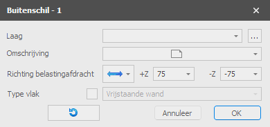
Vervolgens komt het onderstaand dialoogvenster in beeld.
Groep/Laag
Buitenschillen kunnen optioneel in lagen worden getekend. Dit komt overeen met de functionaliteit zoals in AutoCAD. Lagen kunnen zichtbaar of onzichtbaar worden ingesteld. (aan/uit) De namen van de lagen kun je aanpassen. Zie Weergaveopties
Omschrijving van de buitenschil
Optioneel kun je hier een toelichtende omschrijving invoeren.
Richting belastingafdracht
Hier kun je opgeven in welke richting de dragende buitenplaat de belasting afdraagt naar de staven. Er zijn 3 mogelijkheden:

Type vlak
De verschillende vlakken worden automatisch gedetecteerd maar hier kun je zelf ook opgeven welk type vlak is. Je hebt de keus uit: gevel, vrijstaande wand, plat dak, lessenaarsdak, zadeldak en onbekend. Het type vlak is natuurlijk van belang voor o.a. de generatie van windbelastingen.
De x-as van het lokale assenstelsel van de vlakbelasting loopt van het eerste punt naar het tweede punt. Met de weergave optie Assenstelsel vlakbelasting kun je het lokale assenstelsel van de buitenschil zichtbaar maken. Zie Weergaveopties.
Contourrichting omkeren
Met deze functie kun je de richting van de contourlijn ("polylijn") omdraaien. Daarmee beïnvloedt je dus ook het assenstelsel van de buitenschil.
Zorg dat de z-as van alle buitenschillen naar buiten wijzen voordat je de belastinggenerator start!!
Gerelateerde onderwerpen
Wizard
Met de wizard kun je de geometrie en windbelastingen van een eenvoudige hal zeer snel en eenvoudig genereren.
Wizard Dialoogvenster
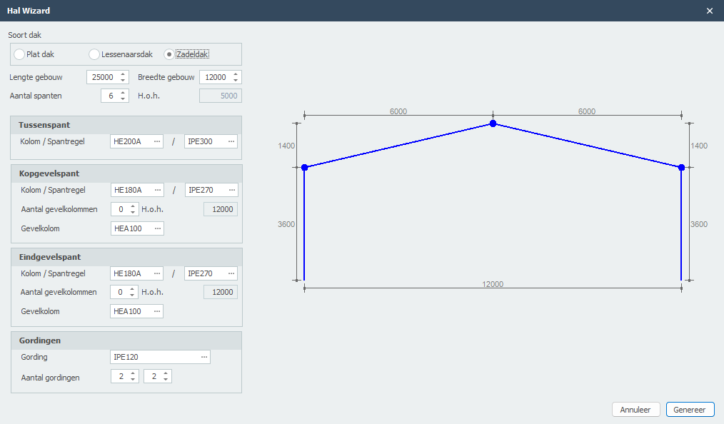
De wizard stelt je in staat om de afmetingen en parameters van je halstructuur in te voeren, en het genereert automatisch de volledige geometrie inclusief balken, kolommen en structurele elementen.
Gegenereerd Resultaat
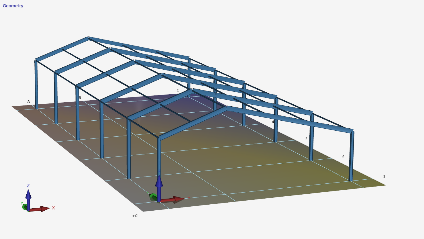
Na het voltooien van de wizard wordt de volledige 3D-structuur automatisch aangemaakt met alle benodigde knopen, balken en verbindingen. Windbelastingen kunnen ook automatisch worden gegenereerd op basis van Eurocode-vereisten.
Gerelateerde onderwerpen
Scharnier in staaf
Een scharnier in een staaf kan eenvoudig worden toegevoegd. Kies in de menubalk voor  In deze modus kun je meerdere scharnieren met behulp van de linker muisknop toevoegen. Bij plaatsing zie je rechtsonder in beeld de coördinaten.
Wanneer je een scharnier plaatst wordt een nieuwe knoop liggend op de staaf gegenereerd en wordt de betreffende staaf opgedeeld in 2 staven met een scharnierende aansluiting. Ook eventuele staafbelastingen worden automatisch verdeeld danwel opgedeeld.
Deze functionaliteit is vooral bedoeld om een gerberligger snel te kunnen invoeren.
Gerelateerde onderwerpen
Belastingen
Belastingen

Alle belastingen (knoopbelasting, staafbelastingen of knoopverplaatsingen) worden per belastinggeval ingevoerd.
Belastingtypes
Gerelateerde onderwerpen
Belastinggenerator
Belastinggenerator

Werken met de belastinggenerator.
Met de belastinggenerator genereer je in een handomdraai alle sneeuw- en windbelastingen, inclusief alle belastingcombinaties. Met name windbelasting volgens Eurocode zijn uitgebreid en daardoor bewerkelijk. De belastinggenerator neemt dat werk uit jouw handen. Er zijn hierbij wel een aantal belangrijke spelregels. Kijk op Spelregels vlakbelasting
Voordat je de belastinggenerator start, zul je eerst alle buitenschillen moeten invoeren.
Bekijk de demo
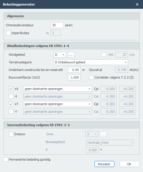
Ontwerplevensduur
De ontwerplevensduur in jaren van de constructie
Imperfecties
Er kan worden ingesteld of met imperfecties rekening moet worden gehouden of niet. In XFEM4U is vooralsnog alleen globale scheefstanden voorzien in 2 richtingen. Er wordt geen rekening gehouden met staafimperfecties (staafuitbuigingen). De spanningscontrole houdt hier rekening mee.
Windbelasting volgens EN-1991-1-4
Windgebied
Afhankelijk van de locatie wordt het windgebied gekozen. Deze waarde verschilt per land.
Terreincategorie
Op basis van lokale omstandigheden wordt de terreincategorie gekozen.
Hoogte maaiveld
De hoogte van het maaiveld in m.
Stuwdruk
Berekende stuwdruk.
Bouwwerkfactor
De bouwwerkfactor volgens art. 6.3.
Correlatie
Instelling of winddrukken op gevels moeten worden gereduceerd met 0,85. E.e.a. volgens Nederlandse NAD art. 7.2.2(3).
Wind +X
Instelling of wind in positieve x-richting moet worden gegenereerd.
Wind -X
Instelling of wind in negatieve x-richting moet worden gegenereerd.
Wind +Y
Instelling of wind in positieve y-richting moet worden gegenereerd.
Wind -Y
Instelling of wind in negatieve y-richting moet worden gegenereerd.
De interne onder- en overdruk is afhankelijk van de grootten van de opening in de gevels.
Sneeuwbelasting volgens EN-1991-1-3
Instelling of sneeuwbelasting moet worden gegenereerd.
A
De hoogte boven zeeniveau [m] is volgens Eurocode tabel C1.
Alle belastingsgevallen en belastingcombinaties voor sneeuw en wind worden automatisch aangemaakt. Je kunt deze belastingen natuurlijk ook wijzigen en uitbreiden.
Gerelateerde onderwerpen
Spelregels vlakbelasting
Om met vlakbelastingen te werken zijn er wel een paar belangrijke spelregels. Wat je moet weten.
-
Om met de belastinggenerator te kunnen werken moeten schillen worden ingevoerd. Vanuit de schillen worden de vlakbelastingen gegenereerd. Schillen moet je vanuit buiten gezien rechtsom tekenen zodat de z-as van het vlak naar buiten is gericht.
-
De schil (en dus ook de vlakbelasting) moet altijd worden "omrand" door vlakdragende staven. Ook al gaat de belasting (door richting belastingafdracht) daar niet naar toe. Heb je een staalconstructie voer dan ook de betonnen funderingstaven in.
-
Werk nauwkeurig. Alle staven / knopen moeten netjes in het vlak van de schil resp. vlakbelasting liggen. Een scheluw vlak wordt niet ondersteund. Dat vereist dus dat je nauwkeurig werkt.
-
Controleer ook altijd of de staafbelastingen vanuit de vlakbelastingen goed worden gegenereerd. Dit doe je door "Afgeleide staafbelastingen" aan te zetten. Controleer daarbij of de richting van de belastingafdracht goed is ingevoerd. Klopt die niet verander dan de richting belastingafdracht bij de schillen en start de belastinggenerator opnieuw.
Belastinggevallen
Belastingsgevallen

Invoeren van belastingsgevallen.
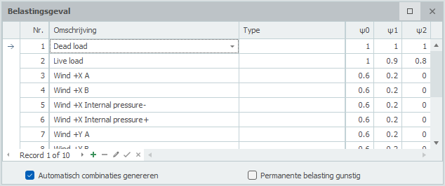
Nr.
Dit nummer wordt automatisch gegenereerd. Je kunt dit niet wijzigen.
Omschrijving
Vrij in te voeren omschrijving van het belastingsgeval.
Type
Het type belasting. Afhankelijk van het type belasting worden volgens de Eurocode de standaard combinatie factoren psi0, psi1 en psi2 bepaald.
Deze combinatiefactoren worden bij het opgeven van de belastingcombinatie als standaard aangeboden. Die kunnen wel worden aangepast.
Standaard worden er automatisch twee belastingsgevallen gegenereerd. Permanent en Veranderlijk.
Automatisch combinaties genereren
Wanneer je belastinggevallen invoert of wijzigt, worden de belastingcombinaties automatisch gegenereerd. Je kunt die natuurlijk ook wijzigen en uitbreiden.
Permanente belasting gunstig
Er worden extra UGT belastingcombinaties gegenereerd waarbij de belastingfactor voor permanente belasting 0,90 is.
Gerelateerde onderwerpen
Volgorde belastingsgevallen
Met rechtermuis knop wordt het onderstaande contextmenu geopend. Met deze functies kun je eenvoudig de volgorde van belastingsgevallen aanpassen en/of belastingsgevallen tussenvoegen.
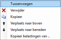
Tussenvoegen
Er wordt een nieuw belastingsgeval aangemaakt en boven het huidige tussengevoegd.
Verwijder
Het belastingsgeval wordt inclusief alle belastingen verwijderd.
Kopieer
Het belastingsgeval wordt inclusief alle belastingen gekopieerd.
Verplaats naar boven / Verplaats naar beneden
Een belasting kan een regel naar boven resp. beneden worden verplaatst.
Gerelateerde onderwerpen
Kopiëren belastingsgeval
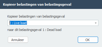
Met rechtermuis knop wordt het onderstaande contextmenu geopend.
Kopieer belastingen van ..
Alle belastingen van een bestaand belastingsgeval kunnen worden gekopieerd. Het onderstaande dialoogvenster wordt geopend. Hierin kies je het belastingsgeval waarvan je de belastingen wilt kopiëren.
Gerelateerde onderwerpen
Staafbelastingen


Staafbelastingen worden in een lokaal Staaf-assenstelsel opgegeven. Zie Tekenafspraak.
Het onderstaande dialoogvenster wordt geopend.
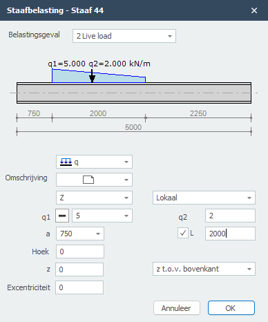
Belastingsgeval
Keuze van het belastingsgeval.
Type belasting
Vrij in te voeren tekst.
| type | omschrijving |
|---|---|
 |
gelijkmatig verdeelde belasting of verlopende belasting |
|
puntlast - F-belasting |
|
moment - M-belasting |
Omschrijving van de belasting
Optioneel kun je hier een toelichtende omschrijving invoeren.
Richting van de belasting / Lokaal-Globaal
De belasting kan in 3 richtingen worden opgegeven. In x-, y- of z-richting ten opzichte van het lokale assenstel (standaard) of het globale assenstelsel.
q1
De grootte van de belasting. Voor q-belasting de grootte van de belasting aan het begin in kN/m. Voor een puntlast de grootte van de belasting in kN, Voor een moment de grootte van de belasting in kNm.
Met 
 kun je het teken van de belasting eenvoudig veranderen. Standaard staat het teken op Dat is het meest voorkomend.
q2
Alleen voor q-belasting de grootte van de belasting aan het eind kN/m.
a
De afstand in mm waar de belasting begint, gerekend vanaf de beginknoop van de staaf.
L
Alleen voor q-belasting de lengte van de belasting. Standaard loopt de belasting tot aan het einde van de staaf.
Hoek
Aleen voor de q- en F-belasting. De hoek in graden met de normaal. Tegengesteld aan de klokrichting is positief.
z
De afstand in z-richting in mm t.o.v. de referentielijn. De referentielijn is instelbaar: 'z- t.o.v. bovenkant' / 'z- t.o.v. zwaartelijn' / 'z- t.o.v. onderkant'.
Deze afstand is alleen relevant voor de toetsing van de kipstabiliteit.
Excentriciteit
De excentriciteit in mm loodrecht gemeten op de belasting (belastingsvlak). Voor een belasting in de z-richting is dit de afstand in y-richting. Voor een belasting in de y-richting is dit de afstand in z-richting. Deze excentriciteit veroorzaakt torsie/wringing in de staaf. Standaard is de excentriciteit nul. Bij bijvoorbeeld balkroosters beton kan de belasting excentrisch aangrijpen.
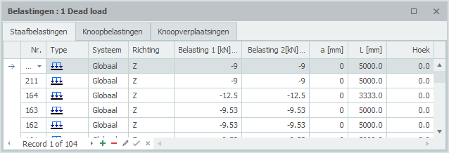
Tabel
Staafbelastingen kunnen ook in de tabel worden toegevoegd en/of gewijzigd. Het maakt niet uit. Ook kun je tussentijds wisselen tussen grafische invoer en tabellarische invoer.
Gerelateerde onderwerpen
Knoopbelastingen

Knoopbelastingen worden in een Knoop-assenstelsel opgegeven. Zie Tekenafspraak.
Het onderstaande dialoogvenster wordt geopend.
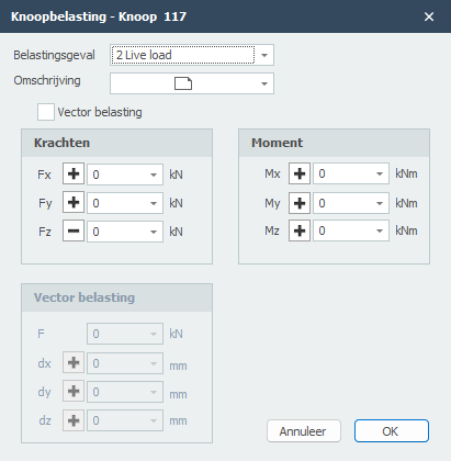
Belastingsgeval
Keuze van het belastingsgeval.
De knoopbelasting wordt standaard in het globale assenstelsel ingevoerd. Wanneer er voor de betreffende knoop een lokale assenstelsel is opgegeven dan worden de krachten t.o.v. van dit assenstelsel opgegeven.
Fx
Grootte van de kracht in kN in x-richting
Fy
Grootte van de kracht in kN in y-richting
Fz
Grootte van de kracht in kN in z-richting
Mx
Grootte van het moment in kNm om x-as.
My
Grootte van het moment in kNm om y-as.
Mz
Grootte van het moment in kNm om z-as.
Vector belasting
Instelling of je de belasting als vector in een bepaalde richting wilt invoeren.
F
Grootte van de vectorkracht in kN
dx
relatieve afstand in x-richting
dy
relatieve afstand in y-richting
dz
relatieve afstand in z-richting
Met dx, dy en dz wordt de richting van de vectorkracht vastgelegd.
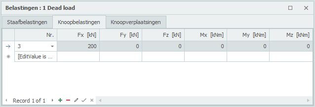
Tabel
Knoopbelastingen kunnen ook in de tabel worden toegevoegd en/of gewijzigd. Het maakt niet uit. Ook kun je tussentijds wisselen tussen grafische invoer en tabellarische invoer.
Gerelateerde onderwerpen
Knoopverplaatsingen (opgelegde verplaatsingen)

Knoopverplaatsingen worden in een Knoop-assenstelsel opgegeven. Zie Tekenafspraak.
Het onderstaande dialoogvenster wordt geopend.
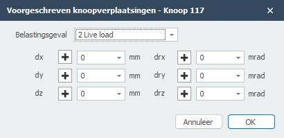
Belastingsgeval
Keuze van het belastingsgeval.
De knoopverplaatsing wordt standaard in het globale assenstelsel ingevoerd. Wanneer er voor de betreffende knoop een lokale assenstelsel is opgegeven dan worden de verplaatsing t.o.v. van dit assenstelsel opgegeven.
dx
Grootte van de verplaatsing in mm in x-richting
dy
Grootte van de verplaatsing in mm in y-richting
dz
Grootte van de verplaatsing in mm in z-richting
drx
Grootte van de rotatie in mrad om x-as.
dry
Grootte van de rotatie in mrad om y-as.
drz
Grootte van de rotatie in mrad om z-as.
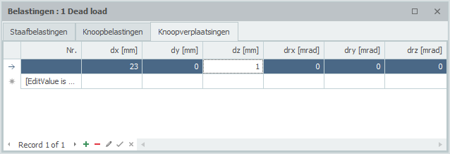
Tabel
Knoopverplaatsingen kunnen ook in de tabel worden toegevoegd en/of gewijzigd. Het maakt niet uit. Ook kun je tussentijds wisselen tussen grafische invoer en tabellarische invoer.
Gerelateerde onderwerpen
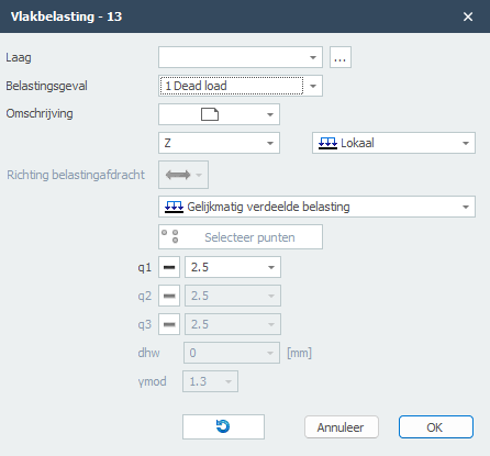
Vlakbelasting

Vlakbelastingen kun je gebruiken voor platen, wanden en staafconstructies. In het geval van staafconstructies worden alle staafbelastingen automatisch gegenereerd. Er zijn hierbij wel een aantal belangrijke spelregels. Kijk op Spelregels vlakbelasting
Bekijk de Demo.
Vlakbelastingen worden als een "polylijn" getekend. Precies zoals dat o.a. ook in AutoCAD gebeurt. Met de escape toets of met de rechter muisknop, beëindig je het tekenen.
Vervolgens komt het onderstaand dialoogvenster in beeld.
Let op! Om de staafbelastingen te kunnen genereren moeten wel randstaven voorkomen.
Met de weergave optie Toon afgeleide staafbelastingen kun je alle automatisch gegenereerde staafbelastingen weergeven. Je kunt hiermee controleren of de belastingen goed zijn aangemaakt. Zie Weergaveopties.
Belastingsgeval
Keuze van het belastingsgeval.
Omschrijving van de belasting
Optioneel kun je hier een toelichtende omschrijving invoeren.
Richting van de belasting / Lokaal-Globaal
De belasting kan in 3 richtingen worden opgegeven. In x-, y- of z-richting ten opzichte van het lokale assenstel (standaard) of het globale assenstelsel.
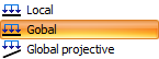
Wanneer je kiest voor Globale projectie (bij sneeuw en veranderlijke belasting) is de belasting gerelateerd aan het projectie-oppervlak. (Bij sneeuw en veranderlijke belasting is dat het grondvlak.)
q1 [,q2 en q3]
De grootte van de belasting in kN/m2.
Richting belastingafdracht
Hier kun je opgeven in welke richting de plaat de belasting afdraagt naar de staven. Er zijn 3 mogelijkheden:
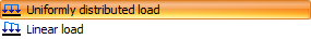
Type belasting
Hier kun je opgeven of de belasting gelijkmatig verdeeld is of lineair verlopend. Met een lineaire verlopende belasting kun je bijvoorbeeld een waterdruk of gronddruk op een wand invoeren. Of een verlopende windbelasting over een hoog gebouw.
Lineair verlopende belasting worden vastgelegd door in 3 punten de belastingen q1, q2 en q3 op te geven. Standaard worden de eerste 3 punten van de contourlijn aangehouden. Met de onderstaande knop kun je ook 3 andere punten van de "polyline" selecteren.
De x-as van het lokale assenstelsel van de vlakbelasting loopt van het eerste punt naar het tweede punt. Met de weergave optie Assenstelsel vlakbelasting kun je het lokale assenstelsel van de vlakbelasting zichtbaar maken. Zie Weergaveopties.
Contour omkeren
Met deze functie kun je de richting van de contourlijn ("polylijn") omdraaien. Daarmee beïnvloedt je dus ook het assenstelsel van de vlakbelasting.
Gerelateerde onderwerpen
Belastingcombinaties
Invoeren van belastingcombinaties
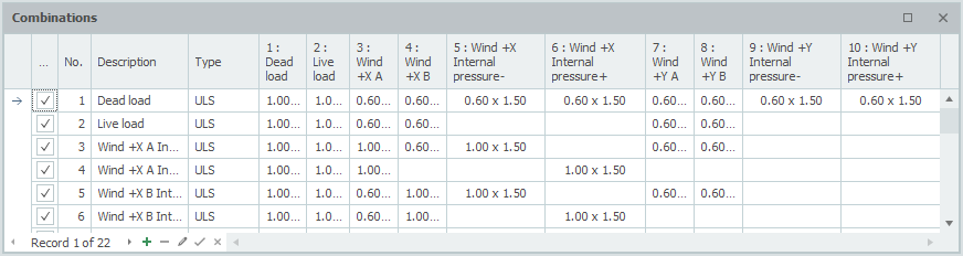
Checkbox
Instelling of de combinatie moet worden berekend of niet.
Nr.
Dit nummer wordt automatisch gegenereerd. Je kunt dit niet wijzigen.
Omschrijving
Vrij in te voeren omschrijving van het belastingcombinatie.
Type
Het type belasting. (UGT - uiterste grenstoestand, UGT- brand, BGT - bruikbaarheidsgrenstoestand., Quasi permanent)
Afhankelijk van het type combinatie worden volgens de Eurocode de standaard waarden aangeboden voor de combinatiefactor (psi) en de belastingsfactor (gamma). Die kunnen wel worden aangepast.
Kolommen met belastingsgevallen
Voor alle aangemaakte belastingsgevallen worden kolommen aangemaakt. Op die manier wordt een tabel zichtbaar waarin je alle combinaties kunt zien. Elk cel bevat 2 getallen in de syntax: combinatiefactor x belastingsfactor. Je kunt nu ook één waarde invoeren en dat is de belastingsfactor. De momentaanfactor wordt in dat geval op 1,00 gezet.
Wanneer je in een cel klikt verschijnt dit dialoogvenster. Hier kun je nu beide waarden aanpassen.
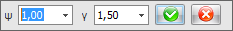
Voor de combinatiefactor en de belastingsfactor worden comboboxen (uitklapscherm) aangeboden met daarin de standaard waarden waaruit je snel kunt kiezen. Je kunt ook zelf een eigen waarde intypen. Dit geeft veel vrijheid.
Wanneer voor één van de waarden een nul wordt ingevuld is het product vanzelfsprekend nul. In dat geval wordt de cel 'leeg' getoond. Dit is alleen om het overzichtelijk te maken.
Standaard worden er automatisch drie belastingcombinaties gegenereerd. (UGT (6.10a), UGT (6.10b) en BGT)
Gerelateerde onderwerpen
Volgorde belastingscombinaties
Met rechtermuis knop wordt het onderstaande contextmenu geopend. Met deze functies kun je eenvoudig de volgorde van belastingscombinaties aanpassen en/of belastingscombinaties tussenvoegen.
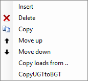
Tussenvoegen
Er wordt een nieuw belastingscombinatie aangemaakt en boven de huidige tussengevoegd.
Verwijder
De belastingscombinatie wordt verwijderd.
Kopieer
De belastingscombinatie wordt gekopieerd.
Verplaats naar boven / Verplaats naar beneden
Een combinatie kan een regel naar boven resp. beneden worden verplaatst.
Kopieer UGT combinaties naar BGT
Alle belastingscombinatie van het type UGT worden gekopieerd als type BGT. De belastingsfactoren worden daarbij op 1.00 gesteld.
Gerelateerde onderwerpen
Bewerken
Bewerken

De sectie Bewerken bevat tools voor het wijzigen, kopiëren en beheren van structurele elementen in het model.
Hoofdfuncties
- Menu - Toegang tot bewerkingscommando's en tools
- Selecties maken - Tools voor het selecteren van meerdere elementen
Overzicht
Het Bewerken-lint biedt uitgebreide tools voor het wijzigen van uw structureel model, waaronder:
- Kopieer- en verplaatsbewerkingen
- Rotatie- en spiegelfuncties
- Array-bewerkingen voor het maken van meerdere kopieën
- Selectietools voor het beheren van elementen
- Ongedaan maken en opnieuw uitvoeren functionaliteit
- Hernummeren van knopen en balken
Gerelateerde onderwerpen
Menu
 Hernummeren
Met deze functie kunnen staven en knopen worden hernummerd.
 Ongedaan maken (Ctrl+Z)
  Opnieuw uitvoeren (Ctrl+Y)
Alle bewerkingen kunnen ongelimiteerd worden teruggedraaid of herhaald. Wil je terug naar een eerdere situatie? Het kan. De herstelfunctie helpt je feilloos en snel.
Een foutieve of onbedoelde invoer kan worden hersteld maar ook kun je met deze functie snel meerdere oplossingen vergelijken. Het helpt je om een optimaal ontwerp te maken van jouw constructie.
Kopiëren
Met deze functie kun je geselecteerde knopen, staven en platen kopiëren. De COPY opdracht wordt herhaald. Je kunt dus op meerdere plekken jouw kopie plaatsen en daarmee nog sneller en makkelijker jouw rekenmodel invoeren. Gebruik de esc-toets of de rechter muisknop om het kopiëren te beëindigen.
 Verwijderen
Met deze functie kun je geselecteerde onderdelen verwijderen.
 Verplaatsen
Met deze functie kun je knopen verplaatsen. Je selecteert de betreffende knopen door afzonderlijk op die knopen te klikken of door gebruik te maken van 'selectievenster (select Window) / kruising (Select Crossing)'. Zie Selecties maken
Vervolgens markeer je het begin door op een bestaande knoop te klikken. (1. Selecteer basispunt) Verplaats nu de muis in de richting waarin je de knopen wilt verplaatsen. (2. Selecteer het tweede punt in de richting waarin je wilt verplaatsen) Terwijl je de cursor verplaatst verschijnt er een maatlijn in één van de hoofdrichtingen x (rood), y (groen) of z (blauw). Je kunt vrijwel net als in AutoCad de afstanden direct ook getalsmatig invoeren door gelijk het getal / de getallen in te typen vanaf jouw toetsenbord. Er zijn 3 mogelijkheden.
1. Verplaatsen met een bekende afstand in één van de hoofdrichtingen
Het getal verschijnt in de maatlijn. Met de enter-toets wordt de invoer afgesloten en worden de knopen verplaatst.
2. Verplaatsen met relatieve cartesische coördinaten (dx, dy, dz)
Eerst voer je de afstand in x-richting in. Het getal verschijnt in de maatlijn. Vervolgens typ je een punt-comma ";" in en de afstand in y-richting. Het getal verschijnt in een 2de invoerveld. Vervolgens typ je een punt-comma ";" in en de afstand in z-richting. Het getal verschijnt in een 3de invoerveld. Met de enter-toets wordt de invoer afgesloten en worden de knopen verplaatst.
3. Verplaatsen met relatieve cartesische coördinaten (dx, dy, dz) of naar absolute cartesische coördinaten (x, y, z)
Druk op de spatiebalk en het onderstaande dialoogvenster verschijnt. Hierin kun je relatieve coördinaten of absolute coördinaten direct invoeren.
 Roteren
Met deze functie kun je geselecteerde onderdelen roteren. Je kunt hiermee ook meerdere kopieën maken.
 Meerdere kopieën
Met deze functie kun je geselecteerde onderdelen een aantal keer kopiëren.
Met deze functie kun je eenvoudig meerdere kopieën maken van geselecteerde knopen, staven en/of platen. Je selecteert de betreffende knopen, staven en/of platen met behulp van het 'selectievenster (select Window) / kruising (Select Crossing)'. Zie Selecties maken.
Vervolgens markeer je het begin door op een bestaande knoop te klikken. (1. Selecteer basispunt) Verplaats nu de muis in de richting waarin je de knopen wilt verplaatsen. (2. Selecteer het tweede punt in de richting waarin je wilt kopiëren) Zie ook Verplaatsen.
Het onderstaande dialoogscherm wordt zichtbaar.
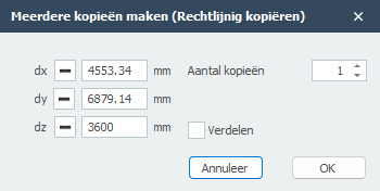
Hier voer je het aantal kopieën in. Met de functie Verdelen kun je de kopieën ook verdelen langs de lijn.
... Submenu
met daarin:
 Spiegelen
Met deze functie kun je geselecteerde onderdelen spiegelen of omklappen. Het spiegelvlak is willekeurig en wordt vastgelegd met 3 punten.
 Gegevens kopiëren
Met gegevens kopiëren worden alle gegevens van de geselecteerde staaf gekopieerd. De cursor verandert in  . Klik nu op de andere staaf om die gegevens over te nemen. Met rechtermuisknop of met ESC wordt deze functie weer uitgezet.
 Staaf opdelen
Met deze functie kun je geselecteerde staven opdelen in meerdere staafdelen.
 Bepaal snijpunten van staven
Met deze functie kun je van de geselecteerde staven snijpunten laten berekenen. Ter plaatse van de snijpunten worden knopen aangemaakt.
 Verleng de staven
Met deze functie kun je de geselecteerde staven verlengen.
 Opsplitsen van staven
Staven kun je opdelen in meerdere staven waarbij ook alle staafbelastingen worden gesplitst. Je selecteert de staaf (staven) en de knoop (knopen) op de staaf en kies voor Opsplitsen van staven.
 Samenvoegen van staaf
Dit is een inverse bewerking van Opsplitsen van de staven.
 Staaforiëntatie omdraaien
Met deze functie kun je van de geselecteerde staven de begin- en eindknoop omdraaien en daarmee de richting van het lokale staafassenstelsel aanpassen.
Maak staafgroep
Specifiek en alleen voor de toetsing van de kipstabiliteit kan een staafgroep worden ingevoerd. Zie Eurocode.
Maak stuklijst
Van alle zichtbare staven wordt een stuklijst aangemaakt die je kunt exporteren naar Excel.
 Contour omdraaien
De richting van de plaatcontour bepaalt ook de richting van de lokale z-as. Met deze functie kun je de draairichting van de plaatcontour omdraaien.
Roteren om de lokale z-as
De richting van de x-as van de plaat is gelijk aan die van de 1e contourzijde. Met deze functie kun je die 1e zijde doorschuiven en kun je daarmee de richting van de x-as aanpassen.
Genereer plaatbelasting
Met deze functie kun je snel een vlakbelasting op de plaat zetten. De contour van de vlakbelasting is dan ook de contour van de plaat.
Gerelateerde onderwerpen
Selecties maken / Meerdere selecties
Selectie maken / meerdere selecties
Om een (groot) aantal knopen, staven, platen of belastingen in één keer te kunnen selecteren kun je gebruikmaken van Select window of Select crossing.
Dit werkt op precies dezelfde wijze zoals je dat misschien ook kent van o.a. AutoCAD.
Een window teken je van links naar rechts. Een crossing teken je van rechts naar links.
'Select window' (van linksonder naar rechtsboven)
- Bepaal met de muis het startpunt van het te tekenen selectie venster. Dit is de linker hoek van het te tekenen venster.
- Druk de linker muisknop in.
- Terwijl je de linker muisknop ingedrukt houdt verplaats je de muis naar rechts. Er wordt een venster in (gedeeltelijk transparant) blauw getekend.
- Wanneer je de linker muisknop vervolgens loslaat worden alle knopen en staven die volledig binnen dit venster vallen geselecteerd.
'Select crossing' (van rechtsboven naar linksonder)
- Bepaal met de muis het startpunt van het te tekenen selectie venster. Dit is de rechter hoek van het te tekenen venster.
- Druk de linker muisknop in.
- Terwijl je de linker muisknop ingedrukt houdt verplaats je de muis naar links. Er wordt een venster in (gedeeltelijk transparant) groen getekend.
- Wanneer je de linker muisknop vervolgens loslaat worden alle knopen die volledig binnen dit venster en staven die gedeeltelijk binnen dit venster vallen geselecteerd.
Multi select
Om meerdere objecten (bijvoorbeeld knopen of staven) te selecteren gebruik je de CTRL-toets. Met de SHIFT-toets kun je objecten weer uit de selectie halen.
Met de CTRL-toets of de SHIFT-toets ingedrukt 'teken' je het selectie venster zoals hierboven beschreven.
Opmerking
In het ribbon menu kun je met de menu functie Selecteren verschillende soorten selecties maken die je ook met bovenstaande functionaliteit kunt veranderen resp. uitbreiden. Kijk bij Beeld.
Demo
Bekijk de demo waarin een aantal mogelijkheden van select window / crossing zichtbaar wordt.
Gerelateerde onderwerpen
Selectie van overlappende objecten
Afhankelijk van de weergave kunnen meerdere objecten achter elkaar liggen. Bij selectie wordt standaard het dichtsbijzijnde object geselecteerd.
Ok. Maar hoe kun je nu een achterliggend object selecteren?
Daar zijn 2 manieren voor:
Methode 1: De 'Q'-toets
Met de 'Q'-toets kun je in een lus door die overlappende objecten bladeren. Elke keer dat je de 'Q'-toets indrukt, wordt achtereenvolgens in een lus een ander object geselecteerd.
Methode 2: Linkermuisknop ingedrukt houden
Houd de linkermuisknop even ingedrukt en er verschijnt een dialoogvenster met een lijst van alle overlappende objecten gesorteerd op diepte. Je kunt vervolgens hier een of zelfs meerdere objecten selecteren. Maak hierbij gebruik van de Shift-toets resp. de Ctrl-toets om de gewenste selectie te maken.
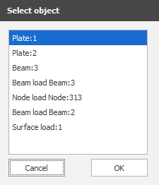
Gerelateerde onderwerpen
Weergave
Beeld

 Selecteren
Dit is een submenu met daarin:
1. Vorige selectie opvragen S
Je kunt met deze optie een vorige selectie weer herhalen. Je kunt dit ook doen met de toets "S" op het toetsenboord. Regelmatig wil je dezelfde selectie nog een keer maken. Met deze optie kun je die laatste selectie weer snel herhalen.
2. Selecteer op coördinatenbereik
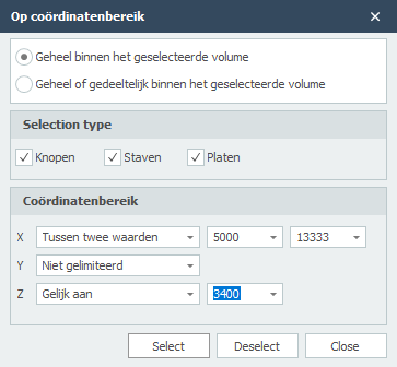
Met deze optie kun je knopen, staven en/of platen selecteren die geheel of gedeeltelijk binnen het geselecteerde volume liggen. De ingestelde waarden worden onthouden en dus kun je die makkelijk aanpasssen voor een volgende selectie.
3. Selecteer staven in XY vlak
4. Selecteer staven in XZ vlak
5. Selecteer staven in YZ vlak
6. Selecteer staven evenwijdig aan
Selecteer alle staven die parallel lopen aan de geselecteerde staaf/staven.
7. Selecteer alle vrije knopen
Selecteer alle knopen die geen onderdeel vormen van het model. Je kunt hiermee die knopen snel verwijderen.
8. Selecteer alles
9. Selectie inverteren
Met deze optie kun je de selectie omdraaien. Je kunt hiermee dus snel alles behalve selecteren.
 Zichtbaarheid
Met zichtbaarheid kun je een selectie van staven en/of platen zichtbaar maken.
Hoe het werkt? Maak een selectie (zie Selectie maken) en klik op deze menu optie "Zichtbaarheid". Alleen de geselecteerde staven en/of platen worden nu getekend. De overige staven en/of platen worden transparant getekend.
Handige tip: Je kunt nu ook een subselectie maken. Hoe? Draai het model maak weer een selectie en druk weer op "Zichtbaarheid".
Om dit ongedaan te maken klik je op deze menu optie zonder dat je een selectie hebt gemaakt.
 Zoeken
Met de functie Zoeken kun je snel en heel eenvoudig een knoop, staaf of profielen opzoeken.
 Meten
Meten
Hiermee kun je afstanden tussen 2 punten (knopen) meten. De afstanden worden in 4 richtingen weergegeven. In x-, y-, z-, en xyz-richting.
 Maatlijn
Je kunt hiermee associatieve maatlijnen tekenen. De maatlijn plaats je met 3 kliks. Je klikt op 2 bestaande knopen en je kiest de positie van de maatlijn. Er wordt automatisch ge-snapt naar eerdere maatlijnen.
 Zoom alles
Met zoom alles wordt de totale constructie beeldvullend met de standaard camera positie weergegeven.
 Zoom selectie
Met zoom selectie wordt de selectie beeldvullend weergegeven. Wanneer er niets is geselecteerd wordt de totale constructie beeldvullend met de laatste camera positie weergegeven.
Line view / Solid
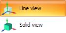
Instelling of: - de schemalijnen en knopen moeten worden getekend (Line view) of dat - alle profielen op ware grootte moeten worden getekend. (Solid view)
 Schermafbeelding
Maak een schermafbeelding. De schermafbeelding wordt gekopieerd naar het klembord (zodat je dat gelijk kunt plakken in jouw MS-Word document), en wordt als bestand ook opgeslagen in de submap "XFEM4U_Images" waar jouw invoer bestand staat, onder de naam "naam van jouw invoerbestand datum tijd.png". Op die manier kun je altijd jouw afbeeldingen terugvinden.
Snapsize
De grootte in mm waarbinnen gezocht wordt naar een bekend punt (knoop/het midden van een staaf/stramienlijn). Standaard is de snapsize ingesteld op 150 mm. Over het algemeen voldoet deze waarde. Zie Snap instellingen
Gerelateerde onderwerpen
Weergaveopties
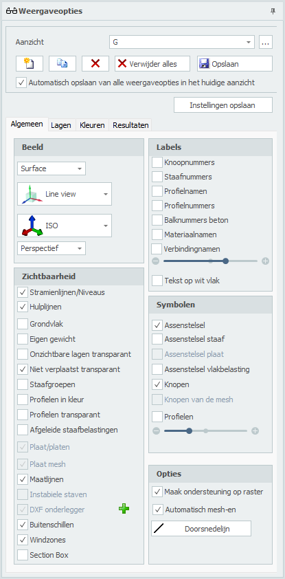
Aanzicht
Optioneel kan een onbeperkt aantal aanzichten worden gemaakt. De camerapositie en alle weergave-instellingen worden per aanzicht opgeslagen. Alle aanzichten worden ook opgeslagen in het projectbestand, zodat ze opnieuw kunnen worden weergegeven en/of kunnen worden opgenomen in de uitvoer wanneer deze opnieuw wordt geopend. De gegenereerde afbeeldingen worden ook opgeslagen als een png-bestand in de submap "XFEM4U_Images" van het projectbestand. Je kunt natuurlijk de naam van het aanzicht aanpassen. In de uitvoerselectie kun je de aanzichten opnemen in de uitvoer of niet. Alle aanzichten van geometrie / belastingen en resultaten worden automatisch op de juiste plaats geplaatst.
Je kunt hier van aanzicht wisselen. Ook kun je hier de naam van het aanzicht aanpassen.

Er wordt een apart dialoogvenster getoond waarin je de volgorde van de aangemaakte aanzichten kunt aanpassen.

Toevoegen van een nieuw aanzicht.

Kopiëren van het huidige aanzicht.

Verwijderen van het huidige aanzicht.
Verwijderen van alle aanzichten.
Opslaan / Bijwerken van een aanzicht. De camerapositie en alle weergave-instellingen worden opgeslagen.
Automatisch opslaan van alle weergaveopties in het huidige aanzicht
Instelling of alle weergaveopties automatisch moeten worden opgeslagen in het aanzicht.
Beeld
Mesh / Surface

Instelling of een mesh of vlakken getekend moet worden.
Line view / Solid
Instelling of: - de schemalijnen en knopen moeten worden getekend (Line view) of dat - alle profielen op ware grootte moeten worden getekend. (Solid view)
Aanzichten
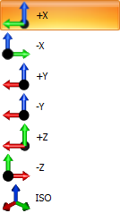
De lijst bevat ook automatisch alle stramienen en niveaus. De diepte is (nog) niet instelbaar en is nu 500mm voor en 500mm achter. Alleen de objecten binnen deze afstanden zullen zichtbaar zijn.

Je kunt het aanzicht veranderen. Standaard wordt ISO ingesteld. Met de instelling Perspective / Orthographic kun je instellen of je perspectief wilt of niet.
Stramienlijnen / Niveaus
Stramienlijnen, niveaus en/of hulplijnen worden gestippeld getekend. Zie Stramienlijnen/Niveaus.
Grondvlak
Instelling of het grondvlak getekend moet worden.
Eigen gewicht
Instelling of de automatisch gegenereerde staafbelastingen a.g.v. het eigen gewicht getekend moet worden in belastingsgevel Permanent.
Onzichtbare lagen transparant
Wanneer bepaalde lagen onzichtbaar zijn ingesteld worden de staven in die lagen niet meer getekend. Met deze instelling kunnen de staven in die onzichtbare lagen toch transparant worden getekend. Dit is zeer handig voor het maken van presentaties.
Niet verplaatst transparant
Instelling of bij het tekenen van de vervormde constructie (Resultaat: doorbuiging) of de niet vervormde constructie transparant getekend moet worden.
Staafgroepen
Staafgroepen die zijn aangemaakt bij de staven (Zie Eurocode) kunnen hiermee grafisch worden weergegeven. Ook de kipsteunen aan de onder- en bovenflens worden hierbij weergegeven.
Profielen in kleur
De verschillende profielen kunnen in kleur worden weergegeven. Elk profiel heeft een eigen kleur. Er kan snel een eenvoudig worden gecontroleerd of alle profielen goed zijn ingevoerd.
Profielen transparant
Alleen in Line view: De profielen worden transparant getekend.
Afgeleide staafbelastingen
Wanneer je een vlakbelasting hebt ingevoerd, kun je met deze optie alle automatisch gegenereerde staafbelastingen weergeven. Je kunt hiermee controleren of de belastingen goed zijn aangemaakt.
Plaat/platen
Instelling of de platen getekend moet worden.
Plaat mesh
Instelling of de plaat mesh getekend moet worden.
Maatlijnen
Instelling of de maatlijnen getekend moeten worden.
Instabiele staven
Laat de staven zien die mogelijk instabiel zijn.
DXF onderlegger
Wanneer je een DXF onderlegger hebt geïmporteerd om snel en gemakkelijk jouw constructie te kunnen invoeren, kun je met deze instelling die onderlegger wel of niet zichtbaar maken.
Buitenschillen
Instelling of buitenschillen wel of niet moeten worden getekend.
Windzones
Wanneer je belastinggenerator hebt gebruikt worden alle windzones getekend. Wil je liever alleen de belastingwaarde zien en niet de zones, zet dan deze instelling uit.
Section Box
Met de Section Box zoals in Revit kun je de zichtbaarheid van het model begrenzen. De objecten van het model binnen de section box zijn nog wel zichtbaar, wat erbuiten valt niet meer. Hiermee kun je dus delen van jouw constructie in beeld brengen maar ook kun je hiermee je werkgebied verkleinen en heb je bijvoorbeeld geen last van snap intelligentie die je soms ook in de weg zit.
Tip. Maak slim gebruik van Section Box. Je zult ervaren dat dat handig en efficiënt is.
Maak ondersteuning op raster
Bij het tekenen wordt automatisch een scharnierende oplegging gegenereerd wanneer de knoop op een rasterpunt ligt.
Automatisch mesh-en
Bij het invoeren van een plaat of wand wordt de plaat resp. wand automatisch ge-mesh-t. Bij kleine modellen is dat zeker handig. Bij grote modellen niet. Het mesh-en van veel aansluitende platen kost relatief veel tijd. Je kunt automatisch mesh-en uitzetten. Dat kan hier bij de weergaveopties en in het dialoogvenster van de plaat. Je kunt nu nog makkelijker jouw platen invoeren. En ben je daar klaar mee dan kun je de platen in één keer mesh-en.
Doorsnedelijn
Bij platen en wanden kun je willekeurig een doorsnedelijn tekenen. In die doorsnede kun je de doorsnedekrachten laten zien. Zie tabblad resultaten.
Labels
Knoopnummers
Knoopnummers worden tussen haakjes (..) bij de knoop weergegeven.
Staafnummers
De staafnummers worden bij de staaf weergegeven.
Profielnamen
De profielnamen worden bij de staaf weergegeven.
Profielnummers
Materiaalnamen
De tekstschaal kan worden ingesteld.
Tekst op wit vlak
Instelling of alle getallen op een witte achtergrond weer te geven. Standaard staat dit uit.
Symbolen
Assenstelsel
Instelling of het hoofdassenstelsel moet worden getekend.
Assenstelsel staaf
Het lokale staafassenstelsel (zie Tekenafspraak) wordt in het midden van de staaf getekend. Dit is met name belangrijk voor het invoeren van de staafbelastingen die in het lokale staafassenstelsel worden ingevoerd. Zie Staafbelastingen.
Assenstelsel plaat
Instelling of het lokale assenstelsel van de plaat moet worden getekend. Zie Platen.
Assenstelsel vlakbelasting
Instelling of het lokale assenstelsel van het belastingvlak moet worden getekend. Zie Vlakbelasting.
Knopen
Alleen in Line view: Instelling of knopen als bolletjes moeten worden getekend.
Profielen
Alleen in Line view: Instelling of een stukje profiel in het midden van de staafschemalijn moeten worden getekend.
De schaal van de symbolen kan worden ingesteld.
Lagen
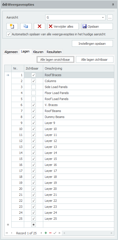
Lagen
Het werken met lagen werkt min of meer gelijk aan AutoCad. Staven kunnen in één of meerdere lagen worden geplaatst. (Zie Staafgegevens) De lagen kunnen wel of niet zichtbaar worden gemaakt. De namen van de lagen kunnen in deze tabel ook worden gewijzigd.
Door slim gebruik te maken van lagen kan de invoer sterk worden vereenvoudigd en houdt de gebruiker overzicht. Ook voor maken van presentatie zijn lagen heel handig.
Tip. Maak slim gebruik van lagen. Je zult ervaren dat dat handig en efficiënt is.
Met de knoppen  en
en  kun je sneller werken. Wil je bijvoorbeeld een laag zien? Zet dan alle lagen uit en dan de betreffende laag aan.
Kleuren
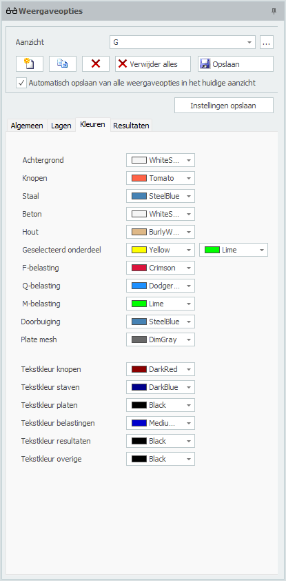
Kleuren
Hier kunnen de kleuren van de verschillende onderdelen worden ingesteld.
Resultaten
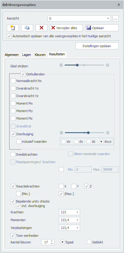
Glad strijken
In de weergave van N-, V-, M-lijnen en vervormingen wordt de staaf opgedeeld in een aantal staafdelen. Dit aantal kan worden gevarieerd van minimaal 3 tot maximaal 30. Standaard staat deze waarde op 10.
Omhullenden
Hiermee is het mogelijk om omhullende Nx-, Vy-, Vz-, Mx-, My-, Mz- en vervormingslijnen weer te geven.
Normaalkracht Nx
Tekening Nx-lijn. De schaal kan worden ingesteld.
Dwarskracht Vy
Tekening Vy-lijn. De schaal kan worden ingesteld.
Dwarskracht Vz
Tekening Vz-lijn. De schaal kan worden ingesteld.
Moment Mx
Tekening Mx-lijn. De schaal kan worden ingesteld.
Moment My
Tekening My-lijn. De schaal kan worden ingesteld.
Moment Mz
Tekening Mz-lijn. De schaal kan worden ingesteld.
Gronddruk
Voor elastisch ondersteunde staven kan een tekening van de grondruk worden weergegeven. De schaal kan worden ingesteld.
Doorbuiging
Tekening vervormingslijn. De schaal kan worden ingesteld.
inclusief waarden
de doorbuigingen worden getalsmatig weergegeven. (alleen bij staven)
Snedekrachten
Instelling of de krachten getalsmatig moeten worden weergegeven.
Alleen maximale waarden
Alleen de absoluut grootste waarden worden weergeven. Hiermee kan het aantal teksten op beeld worden gereduceerd.
Plaatspanningen / -krachten
Tekenen van de plaatspanningen en -krachten in kleur. Links verschijnt een kleurenschaal. Er kan worden ingesteld welke spanning resp. kracht in de plaat moet worden weergegeven. Spanningen kunnen als membraan, buiging of gecombineerd worden weergegeven.
| aanduiding | omschrijving |
|---|---|
| s-x | Spanning in x-richting |
| s-y | Spanning in y-richting |
| t-xy | Schuifspanning |
| s-von Mises | Samengestelde von Mises spanningen |
| nxx | Normaalkracht (membraankracht) in x-richting |
| nyy | Normaalkracht (membraankracht) in y-richting |
| nxy | Schuifkracht in xy-richting |
| mxx | Moment dat spanningen in x-richting geeft |
| myy | Moment dat spanningen in y-richting geeft |
| mxy | Wringmoment |
| vx | Dwarskracht |
| vy | Dwarskracht |
| Mudx | Wood and Armer |
| M'udx | Wood and Armer |
| Mudy | Wood and Armer |
| M'udy | Wood and Armer |
| Asxb | Benodigde wapening in x-richting aan de onderkant (bottom) |
| Asxt | Benodigde wapening in x-richting aan de bovenkant (top) |
| Asyb | Benodigde wapening in y-richting aan de onderkant (bottom) |
| Asyt | Benodigde wapening in y-richting aan de bovenkant (top) |
| Asxb_extra | Benodigde extra wapening op de basiswapening in x-richting aan de onderkant (bottom) |
| Asxt_extra | Benodigde extra wapening op de basiswapening in x-richting aan de bovenkant (top) |
| Asyb_extra | Benodigde extra wapening op de basiswapening in y-richting aan de onderkant (bottom) |
| Asyt_extra | Benodigde extra wapening op de basiswapening in y-richting aan de bovenkant (top) |
| Asw | Benodigde dwarskrachtwapening (verticale beugelwapening) |
| m1 | Hoofdmoment m1 |
| m2 | Hoofdmoment m2 |
| v0 | Maximale dwarskracht v0 |
| Traj-m | Momenttrajectoriën |
| Traj-v | Dwarskrachttrajectoriën |
| Gronddruk | Gronddrukken bij een plaat op een bedding |
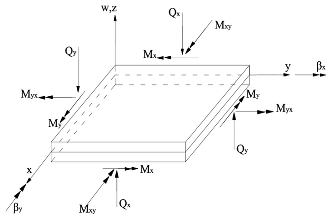
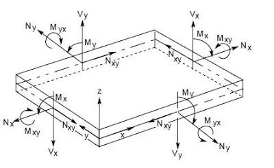
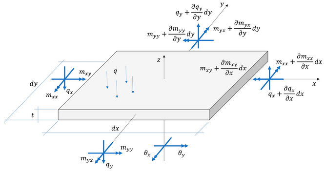
3D Iso-vlakken
De plaatspanningen en -krachten driedimensionaal weergeven.
Doorsnedelijn
Tekenen van de doorsnedekrachten Mnn, Mtt, Mnt, Vn, Vt, Nnn, Ntt or Nnt.
Reactiekrachten
Tekenen van de reactiekrachten in alle steunpunten. Er kan worden ingesteld welke richtingen moeten worden getekend. Standaard worden alle richtingen x,y en z getekend.
Bepalende unity checks
Per staaf kan de maatgevende unity check worden weergeven. Dit is het resultaat van de toetsing volgens Eurocode (staal of hout). Wanneer de unity check kleiner dan 1,00 is voldoet de staaf. Er wordt een groen bolletje getekend.  Wanneer de unity check groter dan 1,00 is voldoet de staaf niet en wordt een rood driehoekje
  getekend.
Min. Max.
Minimale en maximale waarde van de unity check. Alleen staven met een unity check die tussen de minimale en maximale waarde ligt worden grafisch weergegeven.
Door te dubbelklikken op het bolletje resp. driehoekje wordt een gedetailleerde berekening van de betreffende staaf weergegeven.
Krachten
Momenten
Verplaatsingen
Er kan worden ingesteld met hoeveel cijfers achter de komma de waarden moeten worden weergeven.

Gerelateerde onderwerpen
Zoeken
Met de functie Zoeken kun je snel en heel eenvoudig een knoop, staaf of profielen opzoeken.
Hoe werkt dat?
Je kiest voor Knopen, Staven of Profielen. De combobox wordt gevuld met de zichtbare knopen, staven resp. profielen. Het hele model wordt transparant getekend behalve de knoop, de staaf of profielen die je zoekt. Het werkt heel intuïtief.
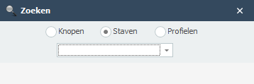
Om te wisselen van knoop of staaf kun je ook in het 3d model klikken op de knoop of staaf.
Gerelateerde onderwerpen
Resultaten
Berekeninginstellingen
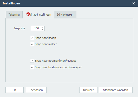
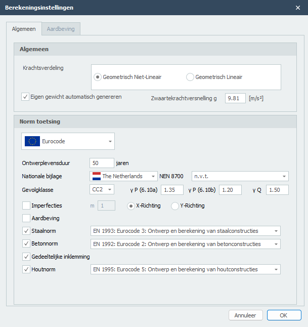
Krachtsverdeling
Je kunt kiezen uit 2 krachtsverdelingen: Geometrisch Niet-lineair (GNL) en Geometrisch Lineair (GL). Wanneer je hebt gekozen voor een norm toetsing volgens Eurocode (hout en staal) zal de krachtsverdeling altijd Geometrisch Niet-lineair (GNL) zijn.
Eigen gewicht
Je kunt instellen of het eigen gewicht automatisch moet worden gegenereerd of niet.
Zwaartekrachtversnelling g
De zwaartekrachtversnelling (of valversnelling) in m/s².
Norm toetsing
Ontwerplevensduur
De ontwerplevensduur van de constructie in jaren.
Nationale bijlage
De nationale bijlage kan per land worden gekozen.
NEN 8700
Partiële belastingsfactoren volgens NEN 8700 tabel A.1.2 bij de beoordeling van de constructieve veiligheid van een bestaand bouwwerk bij verbouw en afkeuren.
Gevolgklasse
De gevolgklasse van de constructie. Deze bepaalt o.a. de te gebruiken belastingsfactoren.
Staalnorm
De te gebruiken staalnorm.
Imperfecties
Er kan worden ingesteld of met imperfecties rekening moet worden gehouden of niet. In XFEM4U is vooralsnog alleen globale scheefstanden voorzien in 2 richtingen. Er wordt geen rekening gehouden met staafimperfecties (staafuitbuigingen). De spanningscontrole houdt hier rekening mee.
m
Alleen voor staalconstructies relevant: Is het aantal kolommen in een rij, met inbegrip van alleen die kolommen die een verticale kracht NEd dragen die niet kleiner is dan 50% van de gemiddelde waarde van alle verticale krachten op de kolommen in het beschouwde verticale vlak.
Aardbeving
Je kunt instellen of een aardbevingsberekening moeten worden gemaakt. Deze functie is vooralsnog alleen voorzien voor Nederland. Zie Aardbeving.
Betonnorm
De te gebruiken betonnorm.
Gedeeltelijke inklemming
Specifiek voor beton kan worden ingesteld of er met toevallige inklemmingsmomenten moet worden gerekend.
Houtnorm
De te gebruiken houtnorm.
Optimalisatie

Met de functie optimalisatie kun je snel en heel eenvoudig het optimale ontwerp maken van jouw staalconstructie. Je kunt hiermee veel staalkilo's besparen.
Hoe werkt dat?
Je doorloopt alle profielen (in de tabel Profielen) zoals je die heeft ingevoerd. Zie Staven. Per profiel worden direct de mogelijke alternatieven weergegeven. Hieruit kun je een ander profiel selecteren.
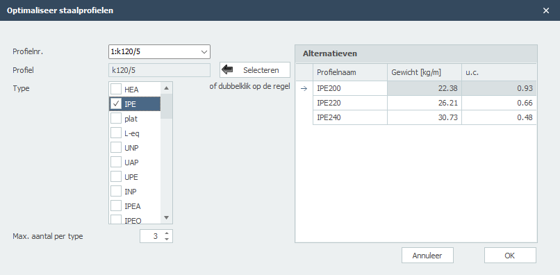
Profielnr.
Het profielnummer verwijst naar het profielnummer in de onderstaande tabel Profielen.
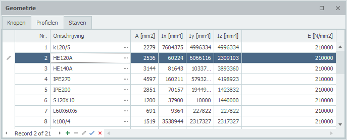
Profiel
Het gekozen profiel.
Type
Hier selecteer je de profieltypen (of groepen) waarbinnen gezocht wordt naar alternatieve profielen.
Max. aantal per type
Het maximaal aantal alternatieven per profieltype. Standaard staat dit aantal op 3 maar Je kunt dit varieren.
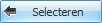
Hiermee kies je profiel uit te rechtertabel "Alternatieven". Je kunt ook dubbelklikken op de regel in de tabel om het profiel te kiezen.
Alternatieven
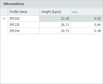
In deze tabel worden direct de mogelijke alternatieven weergegeven. De tabel wordt standaard gesorteerd op unity check (u.c.). Deze unity check is de maatgevende van alle controles volgens Eurocode EN1993.
Je kunt de tabel ook sorteren op Profielnaam of Gewicht door op de Kolomkoptekst te klikken.
Opmerking: Door wijziging van de traagheidsmomenten, wijzigt ook de krachtsverdeling. De optimalisatie houdt hier geen rekening mee. Het kan dus zijn dat de door jou nieuw geselecteerde profielen toch niet voldoen en je opnieuw de optimalisatie moet gebruiken. Toch zul je ervaren dat jouw optimale ontwerp snel en gemakkelijk wordt bepaald.
Aardbeving
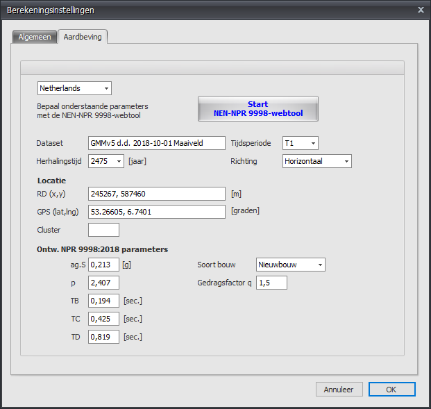
Locatie en de Ontw. NPR 9998:2018 parameters kunnen worden bepaald met NEN NPR 9998-webtool.
Soort bouw
Keuze uit Bestaande bouw/Verbouw/Nieuwbouw. Met de gevolgklasse bepaalt dit de importantiefactor volgens tabel 2.4 van NPR 9998+c1:2020
Gedragsfactor q
Factor gebruikt voor ontwerp- en berekeningsdoeleinden om de krachten in een lineaire berekening te reduceren, dit om rekening te houden met het niet lineaire gedrag van een constructie, gerelateerd aan het materiaal, het constructieve systeem en de ontwerpprocedures.
Een hogere waarde betekent meer reductie en dus een lagere belasting a.g.v. aardbeving.
Zie ook Aardbeving
Bewerken
Bewerken
Het tabblad Bewerken bevat een uitgebreide reeks hulpmiddelen die zijn ontworpen om de geometrie van het structurele model te wijzigen, te repliceren en te verfijnen. Deze hulpmiddelen maken efficiënt beheer van modelelementen mogelijk in verschillende categorieën, waaronder Algemeen, Knopen, Staven en Platen, en zorgen ervoor dat geometrische aanpassingen nauwkeurig en analytisch verantwoord zijn. // image edit_tab
Algemeen
Kopiëren
Functie
Deze functie wordt gebruikt om een enkel duplicaat te maken van geselecteerde modelelementen (zoals knopen, staven of platen) op een gespecificeerde verplaatsing van de oorspronkelijke locatie.
Bediening
- Selecteren: Markeer de elementen die moeten worden gekopieerd.
- Basispunt: Selecteer een referentiepunt op het model als startpunt van de verplaatsing.
- Invoegen: Specificeer de bestemming door op een tweede locatie te klikken of de vereiste afmetingswaarden in te voeren.
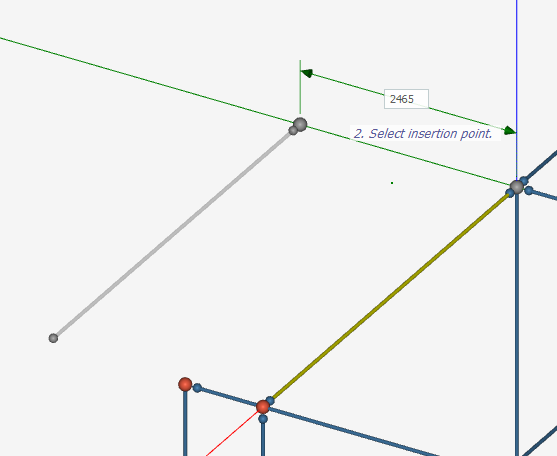
Gerelateerde onderwerpen
Verwijderen
Functie
Deze functie wordt gebruikt om geselecteerde elementen, zoals knopen, staven, platen of belastingen, permanent uit het structurele model te verwijderen.
Doel
De modelgeometrie verfijnen door onnodige of overbodige componenten te elimineren.
Bediening
- Selectie: Gebruik de cursor om op een enkel element te klikken of sleep een selectiekader om meerdere elementen te markeren die je wilt verwijderen.
- Uitvoering: Klik op het pictogram Verwijderen in de groep Algemeen van het tabblad Bewerken.
Gerelateerde onderwerpen
Spiegelen
Functie
Deze functie wordt gebruikt om een symmetrisch duplicaat te maken van geselecteerde modelelementen over een gespecificeerd symmetrievlak.
Bediening
De gebruiker selecteert eerst het/de doelelement(en) en definieert het symmetrievlak door drie verschillende punten in de modelleerwerkruimte te kiezen. Na de ruimtelijke definitie van het spiegelvlak verschijnt een dialoogvenster waarin de gebruiker kan kiezen tussen:
- Omklappen: De originele elementen naar de nieuwe positie verplaatsen
- Spiegelen: De originele elementen behouden en een symmetrische kopie maken
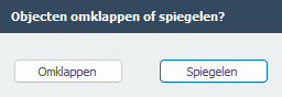
Gerelateerde onderwerpen
Meerdere kopieën
Functie
Deze functie wordt gebruikt om meerdere identieke duplicaten van geselecteerde modelelementen tegelijkertijd te maken langs een lineair pad of een gedefinieerd raster.
Doel
Het automatiseren van de generatie van repetitieve structurele systemen, zoals een reeks identieke verdiepingen in een hoogbouw of een reeks parallelle portaalframes. Deze tool elimineert de noodzaak voor individuele kopieerbewerkingen en zorgt ervoor dat de afstand en uitlijning tussen alle gedupliceerde segmenten perfect uniform blijven.
Bediening
De gebruiker begint met het selecteren van de doelmodelelementen en het definiëren van de translatievector door een basispunt te kiezen gevolgd door een tweede punt om de richting vast te stellen. Deze actie opent het dialoogvenster Meerdere kopieën maken (Lineaire arrays), waar de verplaatsingswaarden (dx, dy, dz) automatisch worden vastgelegd of handmatig kunnen worden aangepast. De gebruiker specificeert vervolgens het "Aantal kopieën" dat moet worden gegenereerd en schakelt indien nodig de optie "Verdelen" in om de kopieën gelijkmatig te verdelen binnen het geselecteerde bereik voordat wordt bevestigd met "OK".
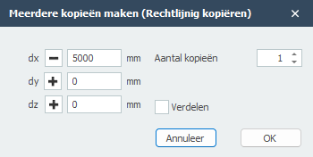
Gerelateerde onderwerpen
Roteren
Functie
Deze functie wordt gebruikt om geselecteerde elementen te roteren rond een gespecificeerde as of een centraal draaipunt met een gedefinieerde hoekstap.
Bediening
De gebruiker definieert eerst de rotatieas door twee verschillende punten in de werkruimte te selecteren. Zodra de as is vastgesteld, verschijnt het dialoogvenster Geroteerd over hoek. In deze interface voert de gebruiker de gewenste "Hoek" van rotatie in. Om nieuwe elementen te maken in plaats van de bestaande te verplaatsen, moet het selectievakje "Kopiëren" worden ingeschakeld, waardoor de gebruiker het "Aantal kopieën" kan specificeren dat rond de as moet worden gegenereerd voordat op "OK" wordt geklikt.
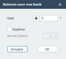
Gerelateerde onderwerpen
Eigenschappen overnemen
Functie
Deze functie wordt gebruikt om de attributen en toewijzingen van een "bron"-element over te dragen naar een of meer "doel"-elementen.
Doel
Consistentie in het model waarborgen en het toewijzingsproces versnellen. In plaats van handmatig gegevens voor elk element opnieuw in te voeren, stelt deze tool gebruikers in staat om snel secties, materialen en lokale oriëntaties te synchroniseren over verschillende delen van de structuur, waardoor het risico op gegevensinvoerfouten wordt verminderd.
Bediening
De gebruiker selecteert eerst het "bron"-element dat de gewenste attributen bevat. Bij het activeren van het commando Eigenschappen overnemen wordt de cursor actief voor doelselectie; de gebruiker klikt vervolgens op het/de "doel"-element(en) waarop de eigenschappen moeten worden toegepast. De software werkt de doelelementen onmiddellijk bij om overeen te komen met de configuratie van de originele bron.
Gerelateerde onderwerpen
Knooppunten
Hernummeren
Functie
Deze functie wijst systematisch numerieke identificatoren opnieuw toe aan alle knopen en balkelementen in het model volgens een gedefinieerde volgordelogica.
Doel
De modeldatabase optimaliseren door een continue, geordende nummeringsreeks te genereren voor alle structurele componenten. Dit verbetert de interne gegevensorganisatie, verhoogt de verwerkingsprestaties en zorgt voor consistente referenties voor analyse, rapportage en interfacing met externe applicaties.
Bediening
Wanneer geactiveerd, vraagt de functie om bevestiging van de gebruiker voordat wordt doorgegaan met de globale hernummeringsbewerking. Bij uitvoering worden alle knopen en staven sequentieel opnieuw geïndexeerd, waarbij hun connectiviteit en eigenschappen behouden blijven terwijl hun identificatienummers worden bijgewerkt.
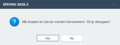
Gerelateerde onderwerpen
Verplaatsen
Functie
Deze functie verplaatst een geselecteerde knoop—samen met alle structurele elementen die ermee verbonden zijn—door een basispunt en een doelpunt te specificeren.
Doel
Een knooppunt en zijn verbonden elementen binnen het model herpositioneren met behoud van alle geometrische relaties, elementeigenschappen en structurele connectiviteit. Dit is essentieel voor het aanpassen van knooplocaties, het verfijnen van geometrie en het uitlijnen van structurele componenten met architectonische indelingen.
Bediening
Selecteer eerst de knoop die moet worden verplaatst. Activeer vervolgens het commando "Verplaatsen" en definieer de translatievector door een basispunt (huidige knooplocatie) te selecteren gevolgd door een tweede punt (doellocatie). De knoop en alle staven, platen en andere elementen die ermee verbonden zijn, worden dienovereenkomstig verplaatst.
Gerelateerde onderwerpen
Coördinaten uitlijnen
Functie
Deze functie wijzigt de coördinaten van geselecteerde knopen door ze uit te lijnen op een specifieke X-, Y- of Z-ordinaatwaarde.
Doel
Geometrische regelmaat afdwingen door knopen langs een rechte lijn in een gespecificeerde globale richting te positioneren. Dit zorgt voor nauwkeurige uitlijning van structurele componenten, vereenvoudigt rastersystemen en corrigeert kleine modelleringsinconsistenties.
Bediening
Selecteer eerst de doelknoop/knopen. Activeer vervolgens het commando en kies de uitlijnas (X, Y of Z) en waarden. De functie past de coördinaten van alle geselecteerde knopen aan zodat ze dezelfde waarde delen langs de gekozen as, gebaseerd op een referentiepunt of door de gebruiker gedefinieerde ordinaat.
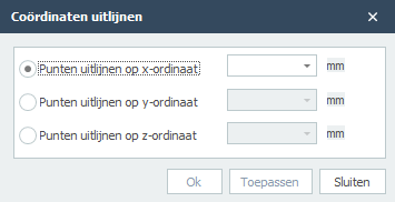
Gerelateerde onderwerpen
Staven
Verdelen
Functie
Deze functie verdeelt een geselecteerd balkelement in twee of meer gelijke segmenten door tussenliggende knopen langs de lengte in te voegen.
Bediening
Selecteer eerst het doelbalkelement. Specificeer vervolgens het gewenste aantal segmenten. De functie voegt automatisch gelijkmatig verdeelde knopen langs de balk in en genereert nieuwe balkelementen ertussen, waarbij de originele dwarsdoorsnede, materiaal en oriëntatie behouden blijven.
Gerelateerde onderwerpen
Snijpunten van staven bepalen
Bereken en maak knopen op balksnijpunten.
Gerelateerde onderwerpen
Staven verlengen
Functie
Deze functie verlengt een geselecteerd balkelement om te snijden met een tweede balk of een referentiepunt, waarbij het eindpunt dienovereenkomstig wordt gewijzigd.
Doel
De balkgeometrie aanpassen zodat deze nauwkeurig verbindt met een ander structureel element of gespecificeerde locatie, waardoor nauwkeurige modellering van kruisingen, steunpunten en continue belastingpaden wordt gewaarborgd.
Bediening
Selecteer eerst de hoofdbalk die moet worden verlengd. Selecteer vervolgens de doelbalk waarnaar deze moet worden verlengd. Het commando herberekent automatisch de eindknooplocatie van de hoofdbalk om een nette kruising met het doel te bereiken, waarbij alle sectie-eigenschappen behouden blijven.
Gerelateerde onderwerpen
Staven splitsen
Functie
Deze functie verdeelt een geselecteerd balkelement op een gespecificeerde knoop langs de lengte, waarbij twee afzonderlijke balksegmenten worden gemaakt.
Bediening
Selecteer eerst de hoofdbalk die moet worden gesplitst. Selecteer vervolgens de knoop langs de balk waar de splitsing moet plaatsvinden. Het commando verdeelt de balk in twee segmenten op die knoop, waarbij elk de eigenschappen van de originele balk erft en de connectiviteit behouden blijft.
Gerelateerde onderwerpen
Staven samenvoegen
Functie
Deze functie combineert twee of meer collineaire balkelementen die een gemeenschappelijke knoop delen tot een enkel, continu balkelement.
Doel
Het structurele model vereenvoudigen door onnodige interne knopen te verwijderen en gesegmenteerde staven samen te voegen tot een verenigd element. Dit vermindert de modelcomplexiteit, verbetert de analyse-efficiëntie en zorgt voor nauwkeurige weergave van continu structureel gedrag.
Bediening
Selecteer eerst de aangrenzende balksegmenten die moeten worden samengevoegd. Het commando verwijdert automatisch de gedeelde interne knoop en creëert een enkel balkelement dat de gecombineerde lengte overspant.
Gerelateerde onderwerpen
Oriëntatie wijzigen
Wijzig de oriëntatie van geselecteerde staven.
Gerelateerde onderwerpen
Balkgroep maken (set staven)
Maak een balkgroep voor kipstabiliteitsanalyse.
Gerelateerde onderwerpen
Platen
Plaatbelasting genereren
Genereer automatisch oppervlaktebelastingen op platen.
Gerelateerde onderwerpen
Roteren om lokale z-as
Functie
Deze functie roteert geselecteerde plaatelementen om hun lokale Z-as, waarbij hun in-plane richting wordt geheroriënteerd terwijl hun positie en verticale uitlijning behouden blijven.
Bediening
Selecteer eerst de doelplaatelementen. Specificeer vervolgens de rotatiehoek om de lokale Z-as. De functie roteert het lokale coördinatensysteem van de plaat terwijl de globale positie en geometrie ongewijzigd blijven.
Gerelateerde onderwerpen
Contour omkeren
Keer de richting van de plaatcontour om.
Gerelateerde onderwerpen
Diversen
Interactieve tabellen
Functie
Deze functie biedt een dynamische spreadsheet-interface voor het bekijken, bewerken en beheren van gestructureerde modelgegevens zoals knoopcoördinaten, elementeigenschappen, belastingen en belastingcombinaties direct binnen de applicatie.
Doel
Efficiënte, bulkbewerking van modelparameters in een tabelformaat mogelijk maken, waardoor nauwkeurige gegevensinvoer, verificatie en import/export-mogelijkheden worden geboden. Dit stroomlijnt grootschalige modelwijzigingen, gegevensvalidatie en integratie met externe tools zoals Microsoft Excel.
Bediening
Open de interactieve tabelinterface, selecteer de gewenste gegevenscategorie (bijv. Knoopcoördinaten, Staven, Belastinggevallen) en bewerk waarden direct in de tabel. Gebruik ingebouwde tools om gegevens naar Excel te sturen voor geavanceerde manipulatie, bijgewerkte gegevens op te halen, kolommen te groeperen en wijzigingen terug toe te passen op het model.
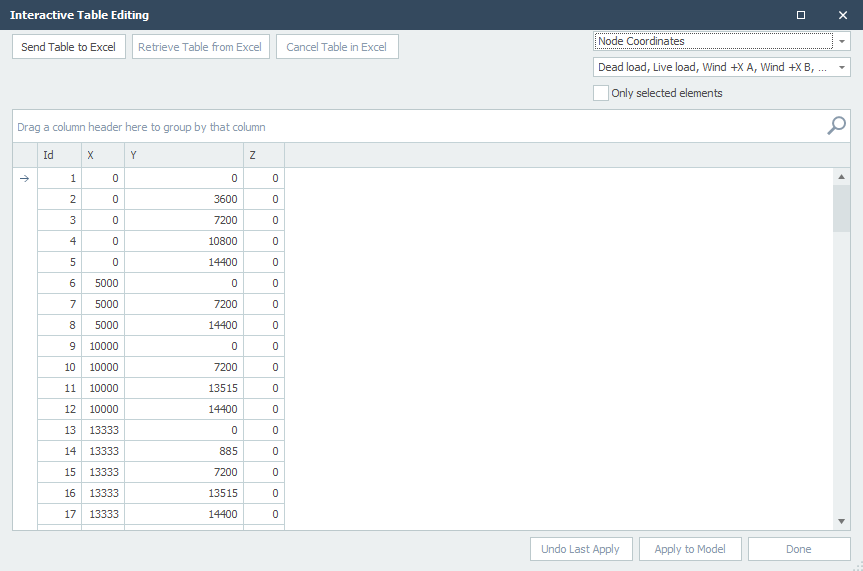
Gerelateerde onderwerpen
Toewijzen
Toewijzen
Het Toewijzen tabblad is de primaire interface voor het toepassen van eigenschappen, randvoorwaarden, belastingen en specifieke gedragsdefinities op de elementen van uw structureel model.
Algemeen
Knopen
Staven
- Profiel
- Staafaansluitingen
- Lokale as
- Optie belastingafdracht
- Staafreferentie
- Kipstabiliteit
- Eigen gewicht
Platen
Algemeen
Toewijzen aan Laag
Functie: Deze functie wordt gebruikt om modelelementen (staven, kolommen, enz.) te organiseren in logische groepen of "lagen" voor visueel beheer, filtering en weergavecontrole.
Werking: Selecteer eerst het element door erop te klikken in het model, en selecteer vervolgens de gewenste Laag uit de lijst door het bijbehorende selectievakje aan te vinken.
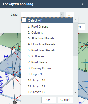
Knooppunten
Knoopoplegging
Functie: Deze functie wordt gebruikt om de steunvoorwaarden en vrijheidsgraden te definiëren bij geselecteerde knopen.
Werking: Specificeer voor geselecteerde knopen de translatie (Tx, Ty, Tz) en rotatie (Rx, Ry, Rz). Definieer in het geval van "S" de veerwaarden voor verende opleggingen. (Kx, Ky, Kz, Cx, Cy, Cz)
A: Absoluut, betekent dat de aansluiting volledig vast is.
P: Positief, alleen trek kan worden overgedragen.
N: Negatief, alleen druk kan worden overgedragen.
S: (Spring) Veer, veerwaarden kunnen worden gewijzigd.
Specificeer daarnaast eventuele excentriciteiten (dx, dy, dz) tussen het knoop en de werkelijke steunlocatie.
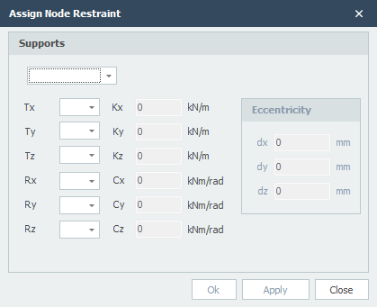
Lokale As
Functie: Deze functie wordt gebruikt om de oriëntatie van het lokale coördinatensysteem te definiëren of te wijzigen bij geselecteerde knooppunten.
Werking: Specificeer voor elk geselecteerde knoop de rotatiewaarden rond de globale X, Y en Z assen om het lokale coördinatensysteem te heroriënteren. De rotaties worden in de opgegeven volgorde toegepast om te transformeren van de globale naar de lokale asoriëntatie.
// link naar assign-node-local-axis afbeelding
Knooppuntbelasting
Functie: Deze functie wordt gebruikt om geconcentreerde krachten en momenten direct toe te passen op knopen.
Werking: Selecteer de knopen en definieer de belastingen in het globale coördinatensysteem. Specificeer krachten (Fx, Fy, Fz) en momenten (Mx, My, Mz) in de gewenste eenheid voor de geselecteerde belastingcase. Kies of je bestaande knoopbelastingen wilt toevoegen, vervangen of verwijderen.
Staven
Profielsectie
Functie: Deze functie stel je in staat om de profielen toe te wijzen.
Werking: Selecteer de gewenste staven in het model en kies vervolgens het juiste profiel.
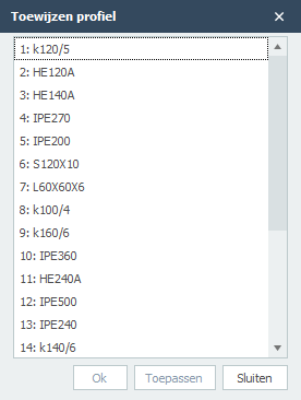
Staafaansluitingen
Functie: Deze functie wordt gebruikt om de staafaansluitingen te definiëren. Met staafaanslutingen kun je verbindingen modelleren, zoals scharnieren, volledig inklemmingen en aangepaste semi-stijve verbindingen.
Werking: Specificeer voor geselecteerde staven de staafaansluitingen bij zowel de begin- als eindknoop (Tx, Ty, Tz, Rx, Ry, Rz). Definieer in het geval van "S" de veerwaarden voor verende aansluitingen. Je kunt ook de knoppen "Momentvast" en "Scharnier" voor veelvoorkomende verbindingstypes. Met de knop "Trekstaaf" kun je snel een trekstaaf definiëren.
A: Absoluut, betekent dat de aansluiting volledig vast is.
P: Positief, alleen trek kan worden overgedragen.
N: Negatief, alleen druk kan worden overgedragen.
S: (Spring) Veer, veerwaarden kunnen worden gewijzigd.
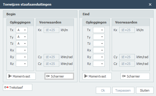
Lokale As
Functie: Deze functie wordt gebruikt om het lokale coördinatensysteem van geselecteerde balkelementen opnieuw te definiëren.
Werking: Selecteer de doelbalkelementen en specificeer vervolgens de bijgewerkte lokale asoriëntatie door rotaties of richtingsvectoren te definiëren ten opzichte van het globale coördinatensysteem.
Belastingafdracht
Functie: Deze functie wordt gebruikt voor de instelling of de staaf vlakbelasting dragend is of niet.
Werking: Selecteer de staven en activeer de optie "Vlakbelasting dragend".
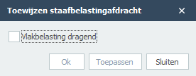
Staafreferentie
Functie: Deze functie wordt gebruikt om de verticale offset van de analytische lijn van een balk ten opzichte van zijn fysieke zwaartepuntas te definiëren. Noot. Dit is alleen tekentechnisch!!!
Werking: Selecteer de doelstaven en specificeer vervolgens de offsetwaarde en selecteer de referentierichting (bijv. Boven, Onder).
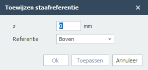
Kipstabiliteit
Functie: De Kipstabiliteit toewijzing wordt gebruikt om de kipafstanden voor staven te definiëren.
Werking: Selecteer de staven en definieer kipafstanden bij de bovenflens, onderflens of beide. Je kunt het aantal kipsteunen, de kipafstanden of de knoopnummers invoeren.
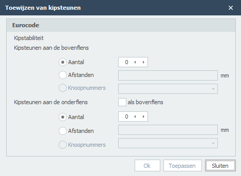
Eigen Gewicht
Functie: Deze functie wordt gebruikt om de instelling van eigen gewicht voor geselecteerde staven te veranderen.
Werking: Selecteer de staven en activeer de optie "Eigen gewicht meenemen". De software berekent het eigen gewicht op basis van de dwarsdoorsnede-eigenschappen van de staaf, materiaaldichtheid en lengte, en past deze vervolgens toe als een verdeelde belasting in de zwaartekrachtrichting.
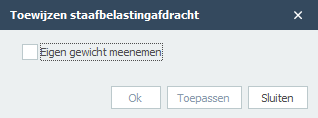
Platen
Automatische Plaat Mesh
Functie: Deze functie wordt gebruikt om een eindige elementen mesh te genereren op plaatelementen met een gespecificeerde doel elementgrootte.
Doel: Om plaatcomponenten te discretiseren in eindige elementen voor structurele analyse. De meshkwaliteit en dichtheid beïnvloeden direct de nauwkeurigheid van spanningsresultaten, vervormingsberekeningen en algehele oplossingsconvergentie in plaatbuigings- en membraangedragssimulaties.
Werking: Selecteer de doelplaatelementen en specificeer de gewenste meshgrootte. De software verdeelt de platen automatisch in eindige elementen (meestal driehoekig of vierhoekig) op basis van de gespecificeerde dimensie, waarbij juiste connectiviteit en geometrische weergave worden gegarandeerd.
//link naar assign-plate-automatic-plate-mesh afbeelding
Selecteren
Selecteren
Dit tabblad biedt uitgebreide tools voor het selecteren van specifieke componenten binnen het structurele model op basis van verschillende criteria en filters. Het georganiseerde filtersysteem stelt gebruikers in staat om snel doelelementen te isoleren op basis van eigenschappen, ruimtelijke relaties of andere attributen, wat de workflow-productiviteit aanzienlijk verbetert.
Algemeen
- Alles selecteren
- Selectie omkeren
- Selectie wissen
- Vorige selectie ophalen
- Op coördinaatbereik
- Alle zwevende knopen
- Op laag
Knopen
Balken
- Alle balken
- Op nummer
- Op materiaal
- Op profielsectie
- Evenwijdig aan
- Verbonden met knopen
- Verbonden met balken
- Op vlak
- Alleen trek
- Starre verbinding
- Dummy
Platen
Belastingpaneel
Algemeen
Alles Selecteren
Functie: Deze functie wordt gebruikt om alle elementen binnen het huidige model of actieve weergave te selecteren.
Werking: Voert een enkele opdracht uit die alle knopen, staven, platen, steunpunten en belastingen binnen het actieve bereik vastlegt, ongeacht type, laag of locatie.
Selectie Omkeren
Functie: Deze functie keert de huidige selectiestatus van alle elementen in het model om.
Werking: Alle momenteel geselecteerde elementen worden gedeselecteerd, en alle niet-geselecteerde elementen worden geselecteerd.
Selectie Wissen
Functie: Deze functie deselecteert alle momenteel geselecteerde elementen in het model.
Werking: Verwijdert de selectie van alle knopen, staven, platen, steunpunten en belastingen, waardoor het model terugkeert naar een staat zonder actieve selecties.
Vorige Selectie Ophalen
Functie: Deze functie herstelt de eerder actieve selectiestatus.
Werking: Roept de laatste selectie op en activeert deze opnieuw voordat de huidige werd gemaakt, waardoor gebruikers snel kunnen terugkeren naar een vorige selectieset.
Selecteer op Coördinatenbereik
Functie: Deze functie selecteert elementen op basis van hun ruimtelijke locatie binnen een door de gebruiker gedefinieerde driedimensionale begrenzingsbox.
Doel: Het isoleren van structurele componenten die binnen een specifiek gebied van het model vallen, waardoor gelokaliseerde bewerking en toewijzingsoperaties binnen een gecontroleerd geometrisch volume mogelijk worden.
Werking: Definieer het selectievolume door minimum en maximum coördinaatlimieten voor de X-, Y- en Z-assen te specificeren. Kies of elementen volledig binnen het volume moeten worden geselecteerd of die het snijden. Filter op elementtype (Knopen, Staven, Platen) om de selectie verder te verfijnen. Gebruik de actie Selecteren of Deselecteren om de huidige selectieset te wijzigen.
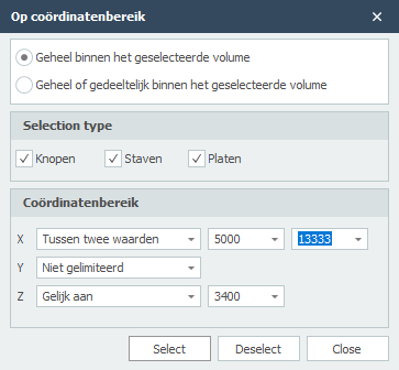
Selecteer Alle Zwevende Knopen
Functie: Deze functie selecteert alle knopen die niet verbonden zijn met structurele elementen.
Werking: Identificeert en selecteert knopen die bestaan in het model maar niet verbonden zijn met staven, platen of andere structurele componenten.
Selecteer op Laag
Functie: Deze functie selecteert alle elementen toegewezen aan een of meer gespecificeerde lagen binnen het model.
Werking: Selecteer uit de lijst van beschikbare lagen de gewenste laag(lagen) door de corresponderende vakjes aan te vinken. De functie zal vervolgens alle knopen, staven, platen of andere elementen markeren die aan die lagen zijn toegewezen.
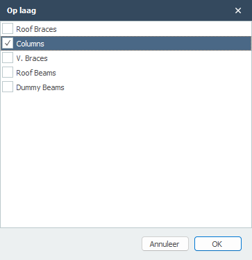
Knooppunten
Alle Knopen Selecteren
Functie: Deze functie selecteert alle knopen in het huidige model.
Werking: Selecteert elke knoop aanwezig in het model, ongeacht hun verbindingsstatus, steunpunten of laagtoewijzing.
Knopen Selecteren op Knoopnummer
Functie: Deze functie selecteert knopen op basis van hun unieke numerieke identificatoren binnen de modeldatabase.
Werking: Voer het gewenste knoopnummer(s) in het invoerveld in of selecteer uit de lijst. De corresponderende knopen worden onmiddellijk geselecteerd in de modelweergave. Gebruik de actie Selecteren of Deselecteren om de huidige selectieset te wijzigen.
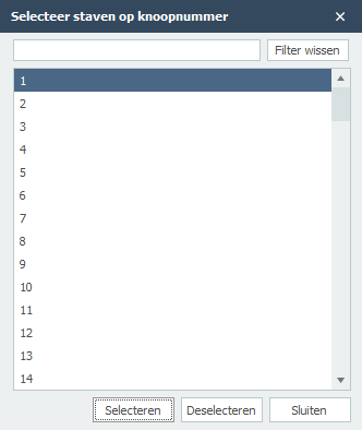
Selecteer Knopen op Knoopsteunpunt
Functie: Deze functie selecteert knopen op basis van hun steunpunt- of vastzetcondities.
Werking: Kies uit verschillende steunpunttypes (vast, scharnier, rol, enz.) om alle knopen te selecteren die de gespecificeerde vastzetcondities hebben toegepast.
Staven
Alle Staven Selecteren
Functie: Deze functie selecteert alle objecten in het model.
Selecteer Staven op Nummer
Functie: Deze functie selecteert specifieke lijnelementen (staven, kolommen, stutten) door hun unieke element identificatienummers in te voeren.
Werking: Voer lijnelement nummers in het selectieveld in of selecteer uit de lijst. Het systeem zal de corresponderende elementen in de modelweergave markeren, waardoor directe toegang tot specifieke structurele componenten mogelijk wordt. Gebruik de actie Selecteren of Deselecteren om de huidige selectieset te wijzigen.
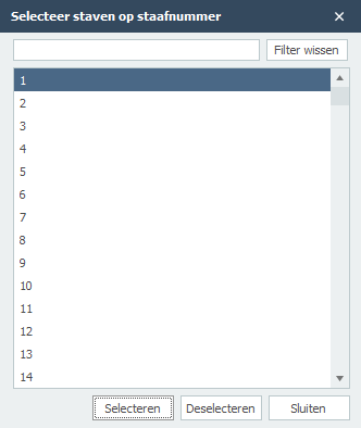
Selecteer Staven op materiaal
Functie: Deze functie selecteert staven op basis van hun toegewezen materiaal.
Werking: Kies de gewenste materiaalnaam uit de beschikbare lijst (bijv. S 235, C20/25). Het systeem zal alle staven markeren die dat materiaal toegewezen hebben. Gebruik de actie Selecteren of Deselecteren om de huidige selectieset te wijzigen.
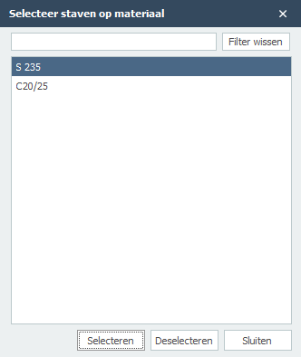
Selecteer Staven op profiel
Functie: Deze functie selecteert staven op basis van hun profiel.
Werking: Kies uit de beschikbare profielen om alle staven te selecteren die het gespecificeerde profiel hebben.
Selecteer Staven Evenwijdig Aan
Functie: Deze functie selecteert staven die evenwijdig zijn aan een gespecificeerde richting of referentiebalk.
Werking: Definieer een richtingsvector of selecteer een referentiebalk om alle staven te vinden en te selecteren die evenwijdig zijn aan de gespecificeerde oriëntatie.
Selecteer Staven Verbonden met Knopen
Functie: Deze functie selecteert staven die verbonden zijn met specifieke knopen.
Werking: Selecteer een of meer knopen om alle staven te vinden en te selecteren die verbonden zijn met die knopen.
Selecteer Staven Verbonden met Staven
Functie: Deze functie selecteert staven die verbonden zijn met andere gespecificeerde staven.
Werking: Selecteer een of meer referentiestaven om alle staven te vinden en te selecteren die knopen delen met de referentiestaven.
Selecteer Staven Op Vlak
Functie: Deze functie selecteert staven die liggen op een gespecificeerd vlak.
Werking: Definieer een vlak door drie punten of een normaalvector en punt te specificeren om alle staven te selecteren die liggen op of coplanair zijn met het gespecificeerde vlak.
Selecteer Staven Alleen Trek
Functie: Deze functie selecteert staven die aangewezen zijn als alleen-trek elementen.
Werking: Identificeert en selecteert alle staven die geconfigureerd zijn om alleen trekkrachten te dragen en geen druk kunnen weerstaan.
Selecteer Staven Starre Verbinding
Functie: Deze functie selecteert staven die aangewezen zijn als starre verbindingen.
Werking: Identificeert en selecteert alle staven die geconfigureerd zijn als starre verbindingen met oneindige stijfheidseigenschappen.
Selecteer Staven Dummy
Functie: Deze functie selecteert staven die aangewezen zijn als dummy elementen.
Werking: Identificeert en selecteert alle staven die geconfigureerd zijn als dummy elementen, typisch gebruikt voor constructiedoeleinden of tijdelijke verbindingen.
Platen
Alle Platen Selecteren
Functie: Deze functie selecteert alle plaatelementen in het huidige model.
Werking: Selecteert elke plaat aanwezig in het model, ongeacht hun materiaal, dikte of laagtoewijzing.
Selecteer Platen op Nummer
Functie: Deze functie selecteert specifieke platen op basis van hun numerieke identificatoren.
Werking: Voer individuele plaatnummers of bereiken in (bijv. 1-10, 15, 20-25) om specifieke platen te selecteren op hun toegewezen nummers.
Selecteer Platen op Materiaal
Functie: Deze functie selecteert plaatelementen op basis van hun toegewezen materiaaleigenschappen.
Werking: Kies de gewenste materiaalnaam uit de beschikbare lijst (bijv. C30/37, S355, Hout C24). Het systeem zal alle platen markeren die dat materiaal toegewezen hebben. Gebruik de actie Selecteren of Deselecteren om de huidige selectieset te wijzigen.
Selecteer Platen Evenwijdig Aan
Functie: Deze functie selecteert platen die evenwijdig zijn aan een gespecificeerd vlak of referentieplaat.
Werking: Definieer een referentievlak of selecteer een referentieplaat om alle platen te vinden en te selecteren die evenwijdig zijn aan de gespecificeerde oriëntatie.
Belastingpaneel
Alle Belastingspanelen Selecteren
Functie: Deze functie selecteert alle belastingspaneelelementen in het huidige model.
Werking: Selecteert elk belastingspaneel aanwezig in het model, inclusief alle verdeelde belastingen, oppervlaktebelastingen en belastingspatronen toegepast op de structuur.
Instellingen & handleiding
Preferences
This section contains user preferences and settings for XFEM4U.
Menu
Menu

Projectgegevens
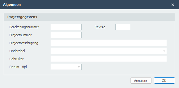
Voorbeeld
Toolbar: 
Het dialoogvenster van afdrukvoorbeeld biedt naast de standaard functionaliteit ook veel extra's waaronder het direct aanmaken van een email met daaraan gekoppeld de berekening in PDF-formaat. Ook kun je vanuit hier een PDF-bestand genereren of een watermerk in jouw uitvoer opnemen.
Uitvoerselectie
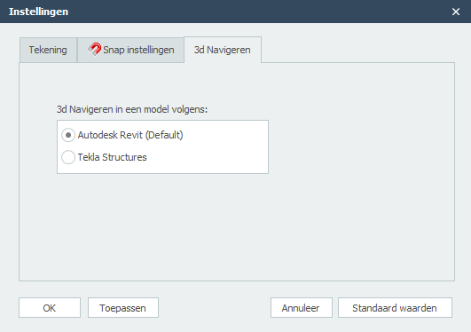
Koptekst
Instelling of de koptekst (header) moet worden afgedrukt.
Voettekst
Instelling of de voettekst (footer) moet worden afgedrukt.
Inhoudsopgave
Instelling of de inhoudsopgave moet worden afgedrukt.
Lagen
Je kunt bepaalde lagen apart uitvoeren.
Aanzichten
Je kunt bepaalde aanzichten in de uitvoer opnemen. De aanzichten worden op de juiste plaats in de uitvoer opgenomen.
Export / Import
Instellingen
Instellingen
Tabblad Instellingen & Help > Instellingen
Het dialoogvenster instellingen bestaat uit 3 tabbladen:
Alle door jouw ingestelde waarden worden opgeslagen in de registries. Wanneer het programma opnieuw wordt gestart worden alle eerder ingestelde waarden gelezen en geactiveerd.
Toepassen
Zonder dat je het dialoogvenster verlaat kun je zien welke effect de instelling heeft.
Let op!. Wanneer je de ingestelde waarden definitief wilt toepassen en bewaren moet je de knop Ok gebruiken.
Standaardwaarden
Alle waarden worden weer teruggezet naar de standaard waarden.
OK
Het dialoogvenster wordt gesloten en alle ingestelde waarden worden toegepast en opgeslagen in de registries.
Annuleer
Het dialoogvenster wordt gesloten en blijven eerdere instellingen van kracht.
Navigeren in 3D
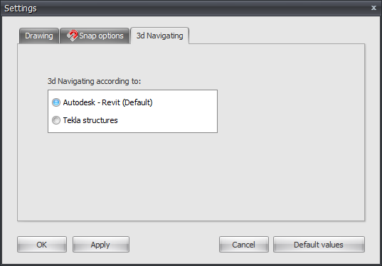
Snap instellingen
Tabblad Instellingen & Help > Instellingen > tabblad Snap instellingen
Wat is de Snap-functie?
Wanneer in het grafische scherm de cursor in de buurt komt van een bekend punt en/of rand, wordt de cursor automatisch naar dit punt verplaatst. Er wordt ge-snapt naar dit punt.
In veel bekende tekenpakketten wordt gebruik gemaakt van deze functionaliteit. Het stel je in staat om een exact punt te selecteren.
Een zeer handige functionaliteit bij het tekenen of verplaatsen van een knoop en/of staaf.
Snapsize
De grootte in mm waarbinnen gezocht wordt naar een bekend punt (knoop/het midden van een staaf/stramienlijn). Standaard is de snapsize ingesteld op 150 mm. Over het algemeen voldoet deze waarde.
Snap naar knoop
Instelling of ge-snapt moet worden naar de dichtsbijzijnde knoop
Snap naar staafmidden
Hier wordt ingesteld of ge-snapt moet worden naar het midden van een staaf. Er wordt een rood rechthoekje zichtbaar wanneer dit punt gevonden wordt.
Snap naar stramienlijnen/niveaus
Stramien en niveaus kunnen worden gebruikt. Hier wordt ingesteld of ge-snapt moet worden naar snijpunten. Knopen volgen de stramienlijnen en niveaus. De knoop wordt lichtgrijs getekend en volgt deze lijnen. Rechtsonderin in beeld zie je de knoopcoördinaten. Je kunt snel een knoop grafisch plaatsen. Vanzelfsprekend kun je ook achteraf de exacte knoopcoördinaten getalsmatig wijzigen. Dubbelklikken op de knoop open een dialoggvenster. Ook kun je in de tabel deze knoopcoördinaten wijzigen, Je klikt op de knoop. De focus wordt direct op de betreffende regel in de knooptabel gezet.
Snap naar bestaande knopen
Alle knopen die zijn ingevoerd worden niet zichtbaar toegvoegd aan de stramienlijn en niveaus. Hierop kan worden ge-snapt. Dit is een zeer handige functionaliteit. Vaak is de geometrie van een constructie regelmatig. Meerdere knopen liggen vaak op dezelfde x- of z-coördinaat. Een constructie kan snel en eenvoudig worden ingevoerd.
Back-up bestanden
Wanneer je een project opslaat, maakt XFEM4U een reservekopie van de vorige versie van het project (dat wil zeggen, het projectbestand vóór de huidige opslag). Deze back-up heeft de naam "backup
Referenties
Mogelijkheden en beperkingen
Mogelijkheden
-
Met XFEM4U kunnen schijven, platen, schalen, balkroosters, vlakke en ruimtelijke staafconstructies kunnen worden berekend.
-
Het programma bepaalt voor een driedimensionale staafconstructie met gekozen stijfheden, de vervormingen en krachtsverdeling onder invloed van knoop- en/of staafbelastingen of voorgeschreven verplaatsingen.
-
De krachtsverdeling wordt bepaald volgens de verplaatsingsmethode, waarbij rekening wordt gehouden met normaal- en dwarskrachtvervorming.
-
Er kan gekozen worden voor lineaire krachtsverdeling (eerste orde) of geometrisch-niet-lineaire krachtsverdeling. (tweede orde)
-
Er zijn zeer veel soorten opleggingen mogelijk. Vanzelfsprekend de bekende en standaard scharnieroplegging, roloplegging en momentvaste oplegging.
-
In XFEM4U kun je echt willekeurig jouw oplegging samenstellen. Verend in de x-richting en star opgelegd in de z-richting, of momentvast en in x-richting vrij, enz. Ook opleggingen die vrij kunnen komen kunnen worden ingevoerd. Bijv. alleen een positieve reactiekracht. Ontstaat een negatieve reactie dan wordt de ’constraint’ vrijgelaten en komt de oplegging vrij. Door gebruik te maken van een lokaal assenstelsel kun je elke willekeurige oplegging onder een willekeurige hoek plaatsen.
-
Staven kunnen 'verend' (d.w.z. met rek- en/of rotatieveren) worden 'aangesloten' aan knopen.
-
Afhankelijk van gekozen run-optie kunnen in een bepaalde belastingscombinatie per staaf extreme momenten en vervormingen, of alle karakteristieken (dwarskracht, moment, hoekverdraaiing en vervorming) worden berekend.
-
Bij een geometrisch-niet-lineaire krachtsverdeling (tweede orde) kan worden gekozen voor een spanningsberekening staal volgens Eurocode 3: EN 1993-1-1, een houtberekening volgens Eurocode 5: EN 1995-1-1 en een betonberekening volgens Eurocode 2: EN 1992-1-1
Beperkingen
Er zijn feitelijk geen beperkingen. Voor het rekenen geldt dat vrijwel alle geheugen dynamisch wordt gealloceerd. Dus (vrijwel) geen keiharde beperkingen (array-dimensies). Behalve dan jouw computer. Echter de grootte van de stijfheidsmatrix en dan met name de “bandbreedte” bepalen wel de limiet. Hoe groot die bandbreedte wordt hangt ook af van het model zelf. Is het een model waarbij het eind vastzit aan het begin, dan kan de bandbreedte groot zijn.
Ontwerp Opstelling
Het programma kent drie rechtsdraaiend assenstelsels :
Hoofdcoördinatenstelsel
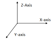
De ligging van dit globale assenstelsel is willekeurig. Het XY-vlak valt samen met het vlak van het raamwerk. Dit assenstelsel wordt gebruikt voor het vastleggen van knoopcoördinaten, knoopbeperkingen en knooppuntsbelastingen. Berekende knooppuntsvervormingen en oplegreacties worden ten opzichte van dit assenstelsel weergegeven.
Staafcoördinatenstelsel
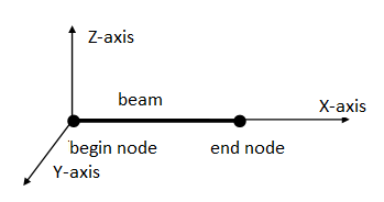
De oorsprong van dit assenstelsel ligt altijd in de beginknoop van betreffende staaf. Het XY-vlak valt samen met het vlak van het raamwerk. De X-as valt samen met de staafas.
Knoopcoördinatenstelsel
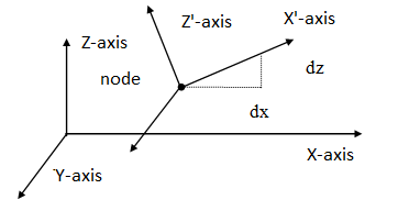
Er kan een lokaal (knoop-)assenstelsel worden opgegeven. De oorsprong ligt in de betreffende knoop. De richting van de X-as wordt bepaald door vanuit de knoop relatief een dx en dz op te geven. (zie bovenstaande figuur). Lokale assenstelsels kunnen worden gebruikt om knoopbeperkingen (opleggingen of ‘restrains’) , knoopbelastingen en/of knoopverplaatsingen in een willekeurige richting op te geven.
De in- en uitvoergegevens worden ten opzichte van de hierboven beschreven assenstelsels weergegeven.
-
Een kracht in de richting van de positieve X- of Z-as wordt als positief beschouwd.
-
Een moment draaiend van de positieve X-as naar de positieve Z-as (volgens kurkentrekker-regel) is positief.
-
Een moment tegengesteld aan de 'klokrichting' is positief.
Achtergrond
Knik - Toetsing volgens de Eurocode
De staaltoetsingen worden in XFEM4U gebaseerd op een geometrisch niet-lineaire krachtsverdeling (2de orde berekening) waarbij ook imperfecties (initiële scheefstanden) automatisch in rekening worden gebracht. Dit is een nauwkeurige rekenwijze en is toepasbaar voor elke (portaal) constructie. Ongesteunde en gesteunde raamwerken.
Of de constructie 'gevoelig' is voor 2de orde effecten volgt rechtstreeks uit de krachtsverdeling. Er hoeft niet meer te worden gerekend met foutgevoelige kniklengtes. De toetsing op (mechanica) knikstabiliteit wordt impliciet in de krachtsverdeling meegenomen.
Hoe verloopt de staalspanningtoetsing volgens Eurocode?
Toelichting:
Volgens Eurocode NEN EN 1993-1-1 art. 5.2.2 (7) a) hoef je geen individuele stabiliteitstoetsing te doen wanneer je alle tweede-orde-effecten (dus ook kip?) in rekening hebt gebracht en gerekend hebt met relevante staafimperfecties. (Algemene initiële scheefstanden en relatief initiële vooruitbuigingen). In XFEM4U wordt wel rekening gehouden met de algemene initiële scheefstanden volgens art. 5.3.2 (3) a). Er wordt echter geen rekening gehouden met relatief initiële vooruitbuigingen volgens art. 5.3.2 (3) b).
Dat betekent dat de individuele stabiliteit van de elementen moet worden getoetst volgens 6.3 waarbij de kniklengte gelijk mag worden gesteld aan de systeemlengte. E.e.a. volgens art. 5.2.2 (7) b). Door toepassing van een geometrisch niet lineaire krachtsverdeling zijn de eindmomenten en krachten natuurlijk inclusief algemene tweede-orde-effecten.
Deze aanpak heeft veel voordelen:
- Er hoeft niet meer te worden gerekend met (soms zeer dubieuze) kniklengten. Kniklengten worden niet in alle gevallen goed berekend en zijn zeker niet belastingonafhankelijk.
- Er hoeft geen keuze gemaakt te worden voor het type raamwerk, geschoord of ongeschoord. Wanneer het raamwerk gevoelig is voor 2de orde volgt dat direct uit de krachtsverdeling.
- Door het raamwerk initieel scheef te zetten verloopt ook bij een symmetrische constructie en symmetrische belasting, het rekenproces (de iteratie) goed.
- Aanpendelende belasting kan eenvoudig in rekening worden gebracht.
- In de stabiliteitstoetsing volgens 6.3.3 wordt ook de kipstabiliteit meegenomen.
Taps verlopende staven
Taps verlopend profiel
Je kunt eventueel een taps verlopend profiel invoeren. Het tabblad "Profiel eind" wordt geactiveerd. Hier kun je het 2de profiel aan het einde van de staaf invoeren. Let op! De basisvorm van het profiel (H-, U-, L-vorm, enz.) moet wel overeenkomen met die van het profiel aan het begin van de staaf.
Krachtsverdeling
Voor de mechanicaberekening wordt de staaf automatisch opgedeeld in een aantal staafdelen met een lengte dat overeenkomt met de gemiddelde profielhoogte. De profielgrootheden zoals traagheidsmoment worden in het midden van elk staafdeel berekend. Per staafdeel wordt gerekend met een constant traagheidsmoment. Doordat de staafdelen vrij kort zijn blijkt deze aanpak voldoende nauwkeurig.
Spanningstoetsing
Voor de spanningscontrole wordt per doorsnede (per x-afstand) de profielgrootheden berekend. Deze berekening is dus exact.
Earthquake
In XFEM4U it is possible to check the structure for earthquakes. Currently this is only provided for the Netherlands.
-
The calculation is based on NEN-NPR 9998+c1:2020.
-
The earthquake parameters that must be entered can be determined with the NEN NPR 9998 web tool.
-
Based on these earthquake parameters, the horizontal elastic response spectrum and the design spectrum are determined.
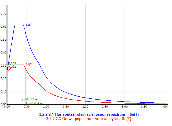
-
For all entered load cases, 2 seismic load cases are automatically generated in x and y direction respectively.
-
Based on the above design spectrum and the natural frequency in x and y direction respectively, all seismic loads in x and y direction are automatically generated.
-
All generated seismic loads are naturally printed in the output including the method by which they were calculated. These loads can also be displayed graphically.
-
The required load combinations for earthquakes are automatically generated.
Natural frequency in x and y direction
The natural frequencies are determined using the Rayleigh method. For the permanent load case, 2 additional load cases are automatically generated. The permanent loads are applied horizontally, based on which the natural frequencies are calculated according to the Rayleigh method. This calculation is also printed in the output.
Buckling - Compatibility Torsion
What is compatibility torsion?
Often torsion contributes little to the force distribution. It is then logical to set the torsional stiffness equal to zero. However, it may be that an element contributes little to the force distribution but must undergo the same deformations as the structure. Torsion that occurs in this process is called compatibility torsion. This can result in a considerable torsional moment in the element, which is only correctly calculated if a realistic torsional stiffness is used.
Reinforced concrete
Reinforced concrete beams without prestressing lose much of their torsional stiffness when the concrete cracks. In some cases, the cracked stiffness can be only 18% of the uncracked stiffness.
Concrete beam grids
If a beam grid is calculated with uncracked torsional stiffness, part of the load will be carried by torsional moments and part by bending moments. However, if the cracked torsional stiffness is used, only small torsional moments will occur and almost all load will be carried by bending moments. In the latter case, we must apply more longitudinal reinforcement but can suffice with much fewer stirrups.
Veelgestelde Vragen (FAQ)
Algemene Vragen
Wat is XFEM4U?
XFEM4U is een structurele analysesoftware ontworpen voor eindige elementen analyse van staven, platen en complexe constructies. Het biedt uitgebreide tools voor modellering, analyse en ontwerpverificatie volgens verschillende bouwcodes waaronder Eurocode.
Hoe kan ik mijn analysecredits upgraden?
Als uw analysecredits te laag worden, wordt u automatisch op de hoogte gesteld. Wanneer u online betaalt, wordt uw accountsaldo onmiddellijk aangevuld. U ontvangt uw factuur via e-mail. Zie ons kenniscentrum voor een handleiding over hoe u uw accountsaldo kunt verhogen.
Wat gebeurt er als ik de software niet sluit maar ondertussen andere programma's gebruik?
Als de software langer dan 1 uur niet wordt gebruikt, worden de berekeningscredits niet afgeschreven. U betaalt alleen voor daadwerkelijk gebruik.
Hoe wordt de gebruikstijd berekend?
U betaalt per minuut - dat wil zeggen, in real time. Het afschrijven van het accountsaldo vindt plaats aan het begin van elk uur. Wanneer de applicatie wordt gesloten, worden de resterende ongebruikte minuten bijgehouden. Deze resterende minuten worden afgetrokken de volgende keer dat het programma wordt gestart. U betaalt dus per minuut dat u de applicatie gebruikt.